507712-01
Page 29 of 36
Issue 1642
Manifold Pressure Measurement
1. Remove the threaded plug from the outlet side of
the gas valve and install a field provided barbed
fitting. Connect to a manometer to measure manifold
pressure.
2. Start unit and allow 5 minutes for unit to reach steady
state.
3. While waiting for the unit to stabilize, observe the
flame. Flame should be stable and should not lift from
burner. Natural gas should burn blue.
4. After allowing unit to stabilize for 5 minutes, record
manifold pressure and compare to value given in
Table 13.
NOTE
:
Shut unit off and remove manometer as soon as an
accurate reading has been obtained. Take care to remove
barbed fitting and replace threaded plug.
Proper Combustion
Furnace should operate a minimum 15 minutes with correct
manifold pressure and gas flow rate before checking
combustion. Take combustion sample beyond the flue out
let and compare to the tables below. The maximum carbon
monoxide reading should not exceed 100 ppm.
Table 12
Capacity
CO²% For Nat
CO²% For LP
-045
7.2 - 7.8
7.5 - 9.0
-070
-090
-110
-135
High Altitude
The manifold pressure may require adjustment to ensure
proper combustion at higher altitudes. Refer to Table 13 for
manifold pressure and pressure switch change.
Other Unit Adjustments
Primary and Secondary Limits
The primary limit is located on the heating compartment
vestibule panel. The secondary limits (if equipped) are
located in the blower compartment, attached to the back
side of the blower. These auto reset limits are factory set
and require no adjustment.
Flame Rollout Switches
This manually reset switches are located on the front of the
burner box.
Pressure Switch
The pressure switch is located in the heating compartment
adjacent to the combustion air inducer. The switch checks
for proper combustion air inducer operation before allowing
ignition trial. The switch is factory set and requires no
adjustment.
Temperature Rise
After the furnace has been started, and supply and return
air temperatures have been allowed to stabilize, check the
temperature rise. If necessary, adjust the blower speed to
maintain the temperature rise within the range shown on
the unit nameplate. Increase the blower speed to decrease
the temperature. Decrease the blower speed to increase
the temperature rise. Failure to adjust the temperature rise
may cause erratic limit operation.
For Safety, shut unit off and remove manometer as
soon as an accurate reading has been obtained. Take
care to replace pressure tap plug.
IMPORTANT
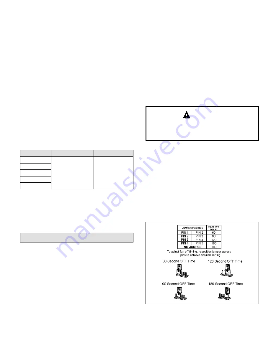
Fan Control
The fan on time of 45 seconds is not adjustable. The heat
fan off delay (amount of time that the blower operates after
the heat demand has been satisfied) may be adjusted by
changing the jumper position across the five pins on the
integrated control. The unit is shipped with a factory fan
off delay setting of 90 seconds. The fan off delay affects
comfort and is adjustable to satisfy individual applications.
Adjust the fan off delay to achieve a supply air temperature
between 90° and 110° F at the moment that the blower
is de-energized. Longer off delay settings provide lower
return air temperatures; shorter settings provide higher
return air temperatures. See Figure 29.
Figure 29. Heat Fan Off Time in Seconds


