507715-01
Page 30 of 61
Issue 1716
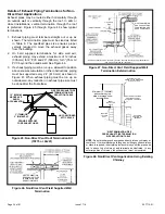
In both Non–Direct Vent and Direct Vent applications, the
vent termination is limited by local building codes. In the
absence of local codes, refer to the current National Fuel
Gas Code ANSI Z223-1/NFPA 54 in U.S.A., and current
CSA-B149 Natural Gas and Propane Installation Codes in
Canada for details.
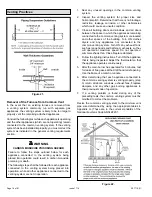
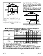
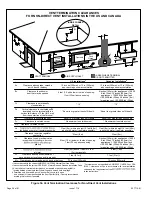
Position termination according to location given in Figure
34 or Figure 35. In addition, position termination so it is
free from any obstructions and 12” above the average
snow accumulation.
At vent termination, care must be taken to maintain
protective coatings over building materials (prolonged
exposure to exhaust condensate can destroy protective
coatings). It is recommended that the exhaust outlet not be
located within 6 feet (1.8 m) of a condensing unit because
the condensate can damage the painted coating.
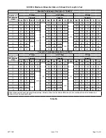
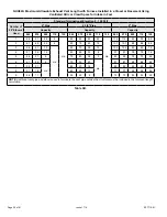
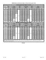
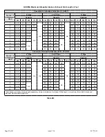
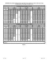
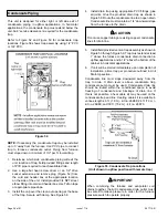
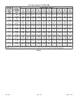
NOTE:
See Table 7 for maximum allowed exhaust pipe
length without insulation in unconditioned space during
winter design temperature is below 32° F (0° C). If required,
exhaust piping should be insulated with 1/2” (13 mm),
Armaflex or equivalent. In extremely cold climate areas with
temperature below 20° F (6.7° C) it is recommended that,
3/4” (19 mm) Armaflex or equivalent be used. Insulation on
outside runs of exhaust pipe may be painted or wrapped
to protect insulation from deterioration in accordance with
the insulation manufacturers recommendation. Exhaust
pipe insulation may not be necessary in some specific
applications.
NOTE:
During extremely cold temperatures, below
approximately 20° F (6.7° C), units with long runs of vent
pipe through unconditioned space, even when insulated,
may form ice in the exhaust termination that prevents the
unit from operating properly. Longer run times of at least 5
minutes will alleviate most icing problems. Also, a heating
cable may be installed on exhaust piping and termination
to prevent freeze-ups. Heating cable installation kits are
available. See unit specification sheets for part numbers.
Do not use screens or perforated metal in exhaust
terminations. Doing so will cause freeze-ups and may
block the terminations.
IMPORTANT
For Canadian Installations Only:
In accordance to CSA International B149 installation
codes, the minimum allowed distance between the
combustion air intake inlet and the exhaust outlet of
other appliances shall not be less than 12 inches (305
mm).
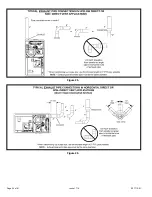
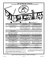
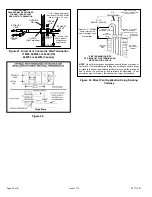
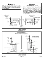
IMPORTANT
Details of Intake and Exhaust Piping
Terminations for Direct Vent Installations
NOTE:
In Direct Vent installations, combustion air is taken
from outdoors and flue gases are discharged to outdoors.
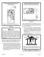
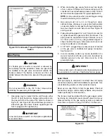
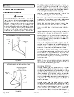
NOTE:
Flue gas may be slightly acidic and may adversely
affect some building materials. If any vent termination
is used and the flue gases may impinge on the building
material, a corrosion-resistant shield (minimum 24 inches
square) must be used to protect the wall surface. If the
optional tee is used, the protective shield is required.
The shield should be constructed using wood, plastic,
sheet metal or other suitable material. All seams, joints,
cracks, etc. in the affected area should be sealed using an
appropriate sealant. See Figure 44.
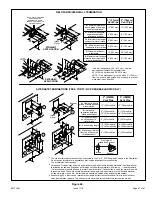
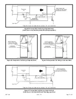
Intake and exhaust pipes may be routed either horizontally
through and outside wall or vertically through the roof. In
attic or closet installations, vertical termination through the
roof is preferred. Figure 36 through Figure 43 show typical
terminations.
1. Intake and exhaust terminations are not required to be
in the same pressure zone. You may exit the intake on
one side of the structure and the exhaust on another
side (Figure 37). You may exit the exhaust out the roof
and the intake out the side of the structure (Figure 38).
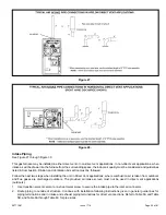
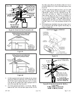
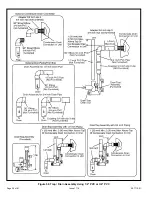
2. Intake and exhaust pipes should be placed as close
together as possible at termination end (refer to
illustrations). Maximum separation is 3” (76 mm)
on roof terminations and 6” (152 mm) on sidewall
terminations.
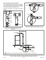
3. On roof terminations, the intake piping should terminate
straight down using two 90° elbows (see Figure 36).
4. Exhaust piping must terminate straight out or up as
shown. A reducer may be required on the exhaust
piping at the point where it exits the structure to
improve the velocity of exhaust away from the intake
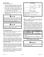
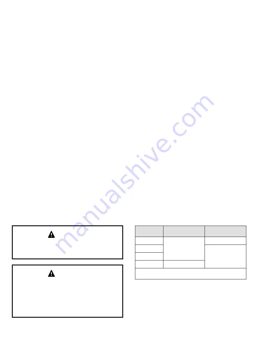
Table 8. Exhaust Pipe Termination Size Reduction
Capacity
Exhaust Pipe Size
Termination Pipe
Size
*045 and 070
2” (51 mm), 2-1/2”
(64 mm), 3” (76 mm)
1-1/2” (38 mm)
*090
2” (51 mm)
110
135
3” (76 mm)
* -045, -070, and -090 units with the flush mount termination
must use the 1 1/2” accelerator supplied with the kit.
NOTE:
Care must be taken to avoid recirculation of
exhaust back into intake pipe.


