background image

107123-01F

For more information, visit www.desatech.com

For more information, visit www.desatech.com

15

15

INSTALLATION

Installing Logs (Cont.)

INSTALLATION

Continued

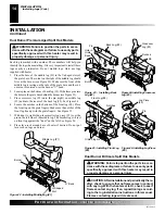
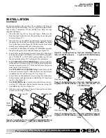
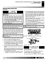
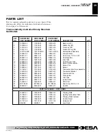
Each log is marked with a number. These numbers will help you
identify the log when installing. It is very important to install these
logs exactly as instructed. Do not modify logs. Only use logs
supplied with heater.
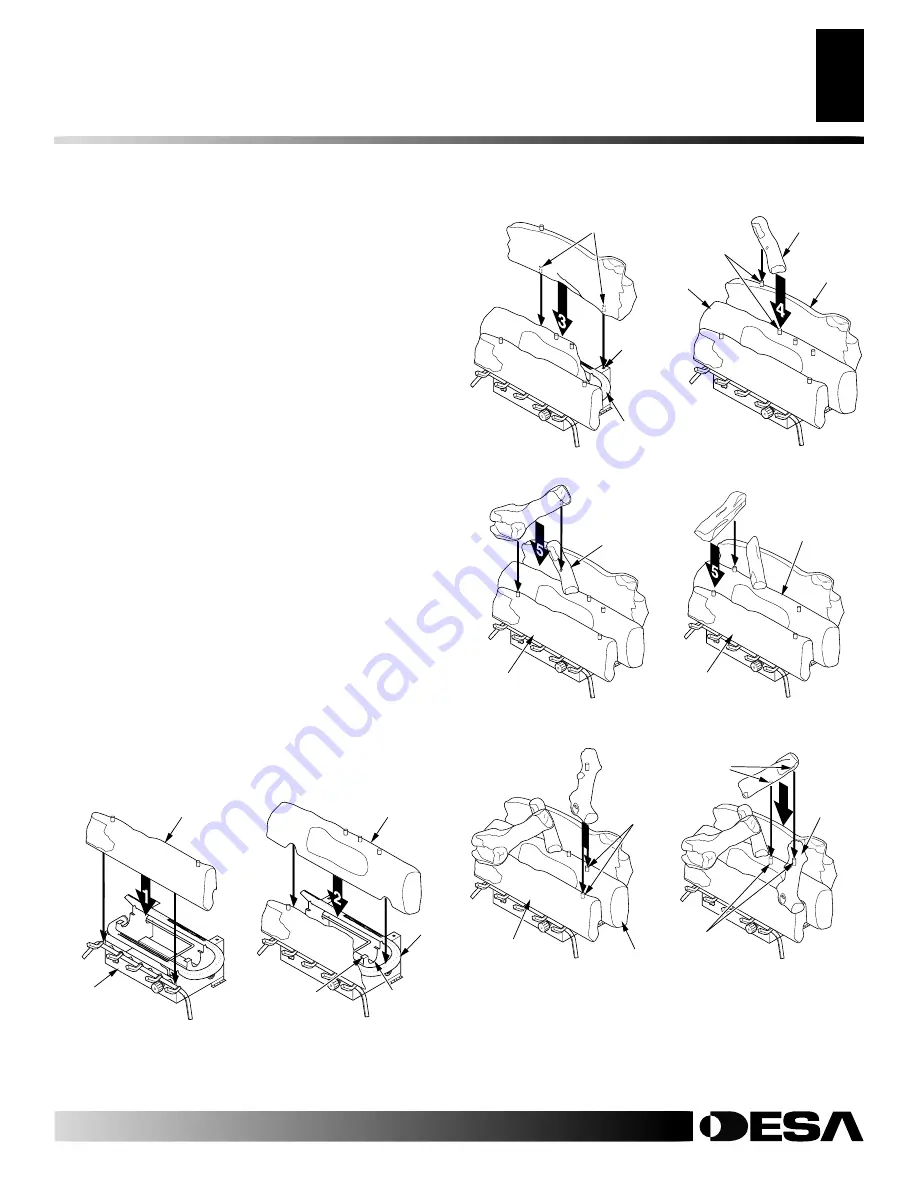
1.

Place the front log (#1) on the grate fingers. Make sure the
front log rests firmly between the grate fingers and the grate
base (see Figure 27).
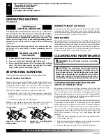
2.

Place the base of the middle log (#2) in the U-shaped slots of
the grate base. The cutout on the right of the middle log should
fit over the burner (see Figure 28). Make sure the front of the
middle log is resting on the tabs of the grate base.
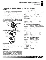
3.

Locate pins on the bottom of back log (#3). Slide these pins into
the holes in the grate base behind the burner (see Figure 29).
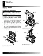
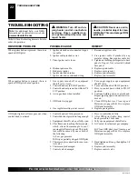
4.

Locate holes on the bottom of crossover log (#4). Slide front
hole onto the left pin (CCL3924NT or CCL3930NTA) or middle
pin (CCL3018NT or CCL3018N) on the middle log (#2) and
the pin on the back log (#3). See Figure 30 for placement.

5.

For CCL3924NT and CCL3930NTA Only:

 Locate pin and hole

on the bottom of crossover log (#5). Slide the pin into the hole
located in crossover log (#4). Slide the hole onto the pin on
front log (#1). See Figure 31.

For CCL3018NT and CCL3018N Only:

 Locate holes on the

bottom of crossover log (#5). Slide the holes over the left pins
on middle log (#2) and front log (#1). See Figure 32.

6.

Locate holes on the bottom of crossover log (#6). Slide these
holes onto the right pins located in middle log (#2) and front
log (#1). See Figure 33.

7.

For CCL3930NTA only:

 Locate holes on the bottom of cross-

over log (#7). Slide onto the pins located in crossover log (#6)
and middle log (#2). See Figure 34.

8.

Add lava rock around base of heater if desired. Do not place
any lava rock on logs or burner.

Figure 27 - Installing Front Log
(#1) (CCL3930NTA Shown)

Front Log (#1)

Grate
Fingers

Grate Base

Figure 28 - Installing Middle Log
(#2) (CCL3930NTA Shown)

Middle Log (#2)

Tab

Burner

U-Shaped
Slot

Figure 29 - Installing Rear Log
(#3) (CCL3930NTA Shown)

Hole in
Grate
Base

Pins

Burner

Figure 30 - Installing Crossover
Log (#4) (CCL3930NTA Shown)

Log #2

Log #3

Pins

Log #4

Figure 31 - Installing Crossover
Log (#5) (CCL3930NTA Shown)

Crossover
Log (#4)

Front Log (#1)

Front
Log (#1)

Crossover
Log (#4)

Figure 32 - Installing Crossover
Log (#5) (CCL3018NT and
CCL3018N Only)

6

Figure 33 - Installing Crossover
Log (#6) (CCL3930NTA Shown)

Pins

Log #2

Front Log (#1)

7

Figure 34 - Installing Crossover
Log (#7) to Model CCL3930NTA
Only

Middle
Log (#2)

Crossover
Log (#6)

Holes

Pins

Summary of Contents for CCL3018N

Page 1: ...n and service must be per formed by a qualified installer service agency or the gas supplier WARNING Improperinstallation adjustment alteration service ormaintenancecancause injury or property damage...

Page 2: ...e fireplace Avoid any drafts that alter burner flame patterns Ceiling fans can create drafts that alter burner flame patterns Altered burner patterns can cause sooting WARNING Do not use a blower inse...

Page 3: ...residues 7 To prevent the creation of soot follow the instructions in Clean ing and Maintenance page 20 8 Before using furniture polish wax carpet cleaner or similar products turn heater off If heate...

Page 4: ...materials increased insulation and new construction methods help reduce heat loss in homes Home owners weather strip and caulk around windows and doors to keep the cold air out and the warm air in Dur...

Page 5: ...ropen ings add the volume of these rooms to the total volume of the space 2 Multiply the space volume by 20 to determine the maximum Btu Hr the space can support __________ volume of space x 20 Maximu...

Page 6: ...From Outdoors Provide extra fresh air by using ventilation grills or ducts You must provide two permanent openings one within 12 of the ceiling and one within 12 of the floor Connect these items dire...

Page 7: ...obacco smoke aromatic candles cleaning fluids oil or kerosene lamps etc in the air exist may discolor walls or cause odors CHECK GAS TYPE Useonlynaturalgas Ifyourgassupplyisnotnaturalgas donotinstall...

Page 8: ...t If so you must always run heater with chimney flue damper open If running heater with damper open noncombustible material above fire place opening is not needed Go to Installing Damper Clamp Accesso...

Page 9: ...o one of the following operate the logs only with the flue damper open raise the mantel to an acceptable height remove the mantel FLOOR CLEARANCES A If installing appliance on the floor level you must...

Page 10: ...ontinued INSTALLATION Installing Damper Clamp Accessory For Vented Operation Installing Heater Base Assembly INSTALLING HEATER BASE ASSEMBLY WARNING If installing in a sunken fireplace special care is...

Page 11: ...ase Assembly to Fireplace Floor Dual Burner Model Figure 14 Attaching Base Assembly to Fireplace Floor Single Burner Model Heater Gas Regulator Flexible Gas Hose if allowed by local codes Figure12 Att...

Page 12: ...ssures In Excess Of 1 2 PSIG 3 5 kPa 1 Disconnect appliance with its appliance main gas valve control valve and equipment shutoff valve from gas supply piping sys tem Pressures in excess of 1 2 psig w...

Page 13: ...fy logs Only use logs supplied with heater CAUTION Afterinstallationandperiodicallythere after check to ensure that no flame comes in contact with any log With the heater set to high check to see if f...

Page 14: ...ee Figure 24 4 Locate the notches in the bottom of the front log 4 Place the front log on the grate fingers Make sure the notches of the front log line up with the grate fingers See Figure 25 5 With k...

Page 15: ...n the bottom of crossover log 5 Slide the pin into the hole located in crossover log 4 Slide the hole onto the pin on front log 1 See Figure 31 For CCL3018NT and CCL3018N Only Locate holes on the bott...

Page 16: ...Make sure log sits forward against the two posts in front of log see Figure 35 This log may be turned to face either direction 2 Place the front log onto grate on front of base assembly The log will...

Page 17: ...cause glass to burst Also if fireplace opening has vents at the bottom you must open the vents before operating heater Youmustoperatethisheaterwithafireplacescreen in place Make sure fireplace screen...

Page 18: ...s appliance has a pilot which must be lighted by hand When lighting the pilot follow these instructions exactly B BEFORE LIGHTING smell all around the appliance area for gas Be sure to smell next to t...

Page 19: ...ge 18 If you don t smell gas go to the next step 5 Turn control knob counterclockwise C clockwise to the PILOT position Press in control knob for five 5 seconds see Fig ure 40 Note You may be running...

Page 20: ...ES Air is drawn into the burner through the holes in the fitting at the entrance to the burner These holes may become blocked with dust or lint Periodically inspect these holes for any blockage and cl...

Page 21: ...ner repeat steps 3 and 4 Clean the pilot assembly also A yellow tip on the pilot flame indicates dust and dirt in the pilot assembly There is a small pilot air inlet hole about two inches from where t...

Page 22: ...ouple damaged 7 Control valve damaged REMEDY 1 Reconnect ignitor cable 2 Free ignitor cable if pinched by any metal or tubing Keep ignitor cable dry 3 Tighten nut holding piezo ignitor to base panel o...

Page 23: ...ter a few hours of operation 1 Refer to Air for Combustion and Venti lation requirements page 4 1 Turn control knob to LO position and let warm up for a minute 2 Operate burner until air is removed fr...

Page 24: ...is lit or shut off Heater produces unwanted odors Heater shuts off in use ODS operates Gas odor even when control knob is in OFF position Gas odor during combustion Logs set cycles to pilot but room...

Page 25: ...nry fireplace see Figure 49 for location If you have a factory built metal fireplace see Figure 50 for location If your fire place has glass doors position sensing bulb directly behind door gap on rig...

Page 26: ...STRATED PARTS BREAKDOWN Variable Manually Controlled CGD3018N CGD3924N CGD3930N CCL3018N CCL3924N 24 3 2 1 4 21 11 12 13 21 8 21 7 10 9 16 15 17 19 22 18 14 19 23 20 18 Smoky Mountain Oak Logs 4a 5 3a...

Page 27: ...Inlet Tube 1 10 102779 03 102779 01 102779 01 Outlet Burner Tube 1 11 099056 26 099056 16 099056 16 Burner Orifice Injector 1 12 102843 01 102843 01 102843 01 Burner Clip 1 13 102980 01 102772 01 1027...

Page 28: ...ation visit www desatech com 28 ILLUSTRATED PARTS BREAKDOWN CGD3018NT CGD3924NT CGD3930NT ILLUSTRATED PARTS BREAKDOWN Thermostatically Controlled Smoky Mountain Oak Models CGD3018NT CGD3924NT CGD3930N...

Page 29: ...867 14 Gas Regulator 1 9 102810 03 102810 03 102810 03 Inlet Tube 1 10 102983 03 102983 01 102983 01 Outlet Burner Tube 1 11 099056 26 099056 16 099056 16 Burner Orifice Injector 1 12 102843 01 102843...

Page 30: ...information visit www desatech com 30 23 23 23 10 8 13 14 15 4 5 1 2 11 12 19 21 21 24 6 7 3 22 20 9 18 23 17 16 ILLUSTRATED PARTS BREAKDOWN Thermostatically Controlled Biltmore Split Oak Model CCL30...

Page 31: ...CK Painted Base Assembly 1 8 102844 02 Lower Bracket 1 9 099211 01 Hex Screw 10 16 x 2 50 2 10 098867 14 Gas Regulator 1 11 102810 03 Inlet Tube 1 12 102983 03 Outlet Burner Tube 1 13 099056 26 Burner...

Page 32: ...nformation visit www desatech com 32 ILLUSTRATED PARTS BREAKDOWN CCL3924NT CCL3930NTA ILLUSTRATED PARTS BREAKDOWN Thermostatically Controlled Biltmore Split Oak Model CCL3924NT CCL3930NTA 9 23 23 23 1...

Page 33: ...Painted Base Assembly 1 10 098867 14 098867 14 Gas Regulator 1 11 102810 03 102981 01 Inlet Tube 1 12 102983 01 102983 01 Outlet Burner Tube 1 13 099056 16 099056 16 Burner Orifice Injector 1 14 1028...

Page 34: ...For more information visit www desatech com 34 ILLUSTRATED PARTS BREAKDOWN Variable Manually Controlled Seasonal Oak Models CRL2718N CRL3124N ILLUSTRATED PARTS BREAKDOWN CRL2718N CRL3124N 4 2 1 3 12...

Page 35: ...7 14 Gas Regulator 1 8 102780 01 102780 01 Outlet Burner Tube 1 9 102798 01 102798 01 Inlet Tube 1 10 099056 20 099056 18 Burner Orifice Injector 1 11 102843 01 102843 01 Burner Clip 1 12 102963 01 10...

Page 36: ...ferral information When calling DESA International have ready model number of your heater the replacement part number TECHNICAL SERVICE You may have further questions about installation operation or t...

Page 37: ...ted College Completed Graduate School 13 Age of Purchaser Under 20 20 29 30 39 40 49 50 59 60 or Over 14 Buyer s total annual household income Under 15 000 15 000 to 19 999 20 000 to 34 999 35 000 to...

Page 38: ...107123 01F For more information visit www desatech com For more information visit www desatech com 38 2701 Industrial Drive P O Box 90004 Bowling Green KY 42102 9004 Postage Required TM TAPE TAPE...

Page 39: ...1 800 446 1446 Fax 616 791 8270 www nbmc com Washer Equipment Co 1715 Main Street Kansas City MO 64108 2195 KS MO AR 816 842 3911 www washerparts com East Coast Energy Products 707 Broadway W Long Bra...

Page 40: ...nsportation and any and all such other costs related to repairing a defective heater will be the responsibility of the owner TO THE FULL EXTENT ALLOWED BY THE LAW OF THE JURISDICTION THAT GOVERNS THE...

Reviews: