


107123-01F
For more information, visit www.desatech.com
For more information, visit www.desatech.com
23
23
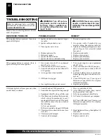
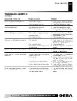
OBSERVED PROBLEM
Burner does light after ODS/pilot is lit
Delayed ignition burner
Burner backfiring during combustion
Slight smoke or odor during initial operation
Moisture/condensation noticed on windows
Heater produces a whistling noise when
burner is lit
White powder residue forming within burner
box or on adjacent walls or furniture
REMEDY
1. Clean burner (see Cleaning and Mainte-
nance, page 20) or replace burner orifice
2. Contact local natural gas company
1. Contact local natural gas company
2. Clean burner (see Cleaning and Mainte-
nance, page 20) or replace burner orifice
1. Clean burner (see Cleaning and Mainte-
nance, page 20) or replace burner orifice
2. Replace damaged burner
3. Replace gas regulator
1. Check burner for dirt and debris. If
found, clean burner (see Cleaning and
Maintenance, pages 20 & 21)
2. Replace gas regulator
3. Problem will stop after a few hours of
operation
1. Refer to Air for Combustion and Venti-
lation requirements (page 4)
1. Turn control knob to LO position and
let warm up for a minute
2. Operate burner until air is removed from
line. Have gas line checked by local
natural gas company
3. Observe minimum installation clear-
ances (see pages 7 through 9)
4. Clean burner (see Cleaning and Mainte-
nance, page 20) or replace burner orifice
1. Turn heater off when using furniture
polish, wax, carpet cleaners, or similar
products
TROUBLESHOOTING
Continued
POSSIBLE CAUSE
1. Burner orifice clogged
2. Inlet gas pressure is too low
1. Manifold pressure is too low
2. Burner orifice clogged
1. Burner orifice is clogged or damaged
2. Damaged burner
3. Gas regulator defective
1. Not enough air
2. Gas regulator defective
3. Residues from manufacturing processes
and logs curing
1. Not enough combustion/ventilation air
1. Turning control knob to HI position
when burner is cold
2. Air in gas line
3. Air passageways on heater blocked
4. Dirty or partially clogged burner orifice
1. When heated, vapors from furniture pol-
ish, wax, carpet cleaners, etc. may turn
into white powder residue
TROUBLESHOOTING


