background image

www.desatech.com

113097-01H

38

REPLACEMENT PARTS

Note:

 Use only original replacement parts. This 

will protect  your  warranty  coverage for parts 

replaced under warranty. 

pARTS UNDER WARRANTY

Contact authorized dealers of this product. If they 

can’t supply original replacement part(s), contact 

your nearest Parts Central (see page 39) or call 

DESA Heating Products’ Technical Service Depart

-

ment at 1-866-672-6040 for referral information.

When calling DESA Heating Products, have ready

•  your name

•  your address

•  model and serial numbers of your heater 

•  how heater was malfunctioning

•  type of gas used (propane/LP or natural gas)

•  purchase date

Usually, we will ask you to return the part to 

the factory.

pARTS NOT UNDER WARRANTY

Contact authorized dealers of this product. If they 

can’t supply original replacement part(s), contact your 

nearest Parts Central (see page 39) or call DESA 

Heating Products at 1-866-672-6040 for referral 

information.

When calling DESA Heating Products, have ready

•  model number of your heater 

•  the replacement part number

ACCESSORIES

Purchase these fireplace accessories from your lo

-

cal dealer. If they can not supply these accessories, 

call DESA Heating Products’ Sales Department at 

1-866-672-6040 for referral information. You can 

also write to the address listed on the back page 

of this manual.

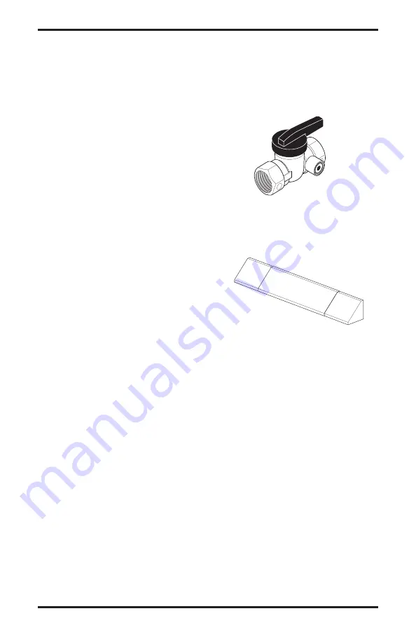
EQUIpMENT SHUTOFF VALVE 
GA5010

For all models. 

Equipment shutoff valve with 1/8" 

NPT tap. Fits 1/2" NPT pipe. 

FIREpLACE HOOD 

GA6050 (Black) 
GA6052 (Brass)
GA6053 (Antique Brass)

For all models.

 Helps deflect heat away from 

mantel or wall above fireplace. 

DAMPER CLAMP - GA6080 
(Not Shown)

Permanently  opens  chimney  flue  damper  for 

vented operation. Can be used only with non-

thermostat accessories.

LAVA ROCK - GA6060  
(Not Shown)

For all models.

 Order when additional rock is 

desired. (2 lb. bag)

Summary of Contents for CCL3018NA

Page 1: ...fire or explosion may result causing property damage personal injury or loss of life Do not store or use gasoline or other flammable vapors and liquids in the vicinity of this or any other appliance WHAT TO DO IF YOU SMELL GAS Do not try to light any appliance Do not touch any electrical switch do not use any phone in your building Immediatelycallyourgassupplierfromaneighbor s phone Follow the gas...

Page 2: ...n 5 Unpacking 5 Product Features 5 Air for Combustion and Ventila ion 5 Installation 8 Operating Heater 19 Inspecting Burners 23 Cleaning and Maintenance 23 Service Hints 24 Technical Service 24 Troubleshooting 25 Optional Positioning of Thermostat Sensing Bulb 28 Specifications 29 Illustrated Parts Breakdown and Parts List 30 Replacement Parts 38 Accessories 38 Parts Central 39 Warranty Informati...

Page 3: ...r its controls can be dangerous WARNING Donotallowfans toblowdirectlyintothefireplace Avoidanydraftsthatalterburner flame patterns Ceiling fans can create drafts that alter burner flame patterns Altered burner patterns can cause sooting SAFETY INFORMATION Continued WARNING Donotuseablow er insert heat exchanger insert orotheraccessorynotapproved for use with this heater Due to high temperatures th...

Page 4: ...the vapors from these products may create a white powder residue within burner box or on adjacent walls or furniture 12 This heater needs fresh outside air ventilation to run properly This heater has an Oxygen De pletion Sensing ODS safety shutoff system The ODS shuts down the heater if not enough fresh air is available See Air for Combustion and Ventilation page 5 If heater keeps shutting off see...

Page 5: ...ir for Combustion and Ventilation WARNING This heater shall not be installed in a confined space or unusually tight con struction unless provisions are provided for adequate combus tionandventilationair Readthe following instructions to insure proper fresh air for this and other fuel burning appliances in your home Today s homes are built more energy efficient than ever New materials increased ins...

Page 6: ... whose volume is less than 50 cubic feet per 1 000 Btu per hour 4 8 m3 per kw of the aggregate input rating of all appliances installed in that space and an unconfined space as a space whose volume is not less than 50 cubic feet per 1 000 Btu per hour 4 8 m3 per kw of the aggregate input rating of all appliances installed in that space Rooms com municating directly with the space in which the appl...

Page 7: ...Section5 3 or applicable local codes VENTILATION AIR Ventilation Air From Inside Building This fresh air would come from an adjoining un confined space When ventilating to an adjoining unconfined space you must provide two perma nent openings one within 12 of the ceiling and one within 12 of the floor on the wall connecting the two spaces see options 1 and 2 Figure 2 You can also remove door into ...

Page 8: ... If not drafting may cause pilot outage or sooting Use a heat resistant sealant Do not seal chimney flue damper WARNING Never install the heater in a bedroom or bathroom unless installed as a vented appliance Variable Manually Controlled Models Only see page 11 in a recreational vehicle where curtains furniture clothing or other flammable objects are less than 42 from the front top or sides of the...

Page 9: ...mum clearances to combustible materials B Clearances from the top of the fireplace open ing to the ceiling should not be less than 42 INSTALLATION Continued Figure 4 Minimum Clearance for Combustible to Wall Minimum 16 from Side Wall Example NOTICE Manual control heaters maybeusedasaventedproduct Ifso youmustalwaysrunheater with chimney flue damper open If running heater with damper open noncombus...

Page 10: ...ow minimum clearances shown in Figure 7 page 11 when using hood NOTICE Surface temperatures ofadjacentwallsandmantelsbe comehotduringoperation Walls and mantels above the firebox may become hot to the touch If installed properly these tem peratures meet the requirement ofthenationalproductstandard Follow all minimum clearances shown in this manual INSTALLATION Continued Noncombustible Requirements...

Page 11: ...e Figure 8 B If combustible materials are less than 14 to the fireplace you must install appliance at least 5 above the combustible flooring see Figure 9 INSTALLING DAMPER CLAMP ACCESSORY FOR VENTED OPERATION Note When used as a vented heater appliance must be installed only in a solid fuel burning fireplace with a working flue and constructed of noncombustible material For Massachusetts Residents...

Page 12: ...id nicks or sharp bends in thermostat bulb wire Keep thermostat bulb in mounting bracket until ready to mount base to floor See Optional Positioning Of Thermostat Sensing Bulb page 28 Installation Items Needed hardware package provided with heater approved flexible gas hose not provided if allowed by local codes sealant resistant to propane propane LP gas not provided electric drill with 3 16 dril...

Page 13: ...nection to the pressure regulator WARNING A qualified ser vicepersonmustconnectheater to gas supply Follow all local codes CAUTION Never connect heaterdirectlytothepropane LP supply This heater requires an externalregulator notsupplied Install the external regulator be tweentheheaterandpropane LP supply WARNING Never connect natural gas fireplace to private non utility gas wells This gas is common...

Page 14: ... that is resistant to liquid petroleum LP gas We recommend that you install a sediment trap in supply line as shown in Figure 15 Locate sediment trap where it is within reach for cleaning Install in piping system between fuel supply and heater Locate sediment trap where trapped matter is not likely to freeze A sediment trap traps moisture and contaminants This keeps them from going into heater con...

Page 15: ...gas or using compressed air 3 Check all joints from gas meter to equipment shutoff valve for natural gas or propane LP supply to equipment shutoff valve for pro pane LP see Figures 17 and 18 Apply noncorrosive leak detection fluid to all joints Bubbles forming show a leak 4 Correct all leaks at once Pressure Testing Heater Gas Connections 1 Open equipment shutoff valve see Figure 16 2 Open main ga...

Page 16: ...he front log 1 on the grate fingers Make sure the front log rests firmly between the grate fingers and the grate base see Figure 19 2 Place the base of the middle log 2 in the U shaped slots of the grate base The cutout on the right of the middle log should fit over the burner see Figure 20 Make sure the front of the middle log is resting on the tabs of the grate base 3 Locate pins on the bottom o...

Page 17: ... front log 1 See Figure 25 for CCL3924PTA NTA or CCL3930PTB NTB See Figure 24 for CCL3018PA NA or CCL3018PTA NTA 7 For CCL3930PTB NTB only Locate holes on the bottom of crossover log 7 Slide onto the pins located in crossover log 6 and middle log 2 See Figure 26 8 Add lava rock around base of heater if de sired Do not place any lava rock on logs or burner Figure 23 Installing Crossover Log 5 CCL39...

Page 18: ...nt of log see Figure 27 This log may be turned to face either direction 2 Place front log onto grate on front of base as sembly The log will fit down between grate fingers and posts on front of base assembly see Figure 28 This log may be turned to face either direction 3 Place the left and right crossover logs on top of the back log and front log Make sure pins on front and back are inserted into ...

Page 19: ...o replace any part of the control system and any gas control which has been under water LIGHTING INSTRUCTIONS WARNING If fireplace has glass doors never operate this heater with glass doors closed If you op erateheaterwithdoorsclosed heat buildup inside fireplace willcauseglasstoburst Make suretherearenoobstructions across openings of fireplace You must operate this heater with a fireplace screen ...

Page 20: ...HI and LO 9 To leave pilot lit and shut off burners only turn control knob clockwise to the HI position then press in and turn clockwise to PILOT position WARNING Do not operate heater between PILOT and HI positions OPERATING HEATER Continued Figure 30 Control Knob and Ignitor Button Location Ignitor Button Control Knob Figure 31 Pilot Thermocouple Pilot Burner Ignitor Electrode VARIABLE CONTROL O...

Page 21: ... part of the control system and any gas control which has been under water OPERATING HEATER Continued LIGHTING INSTRUCTIONS WARNING If fireplace has glass doors never operate this heater with glass doors closed If you op erateheaterwithdoorsclosed heat buildup inside fireplace willcauseglasstoburst Make suretherearenoobstructions across openings of fireplace You must operate this heater with a fir...

Page 22: ...to desired heating level The burners should light Set control knob to any heat level between HI and LO 9 Turn control knob clockwise to the PILOT position to shut off burner leaving pilot lit OPERATING HEATER Continued TO TURN OFF GAS TO APPLIANCE 1 Turn control knob clockwise to the OFF position 2 Close equipment shutoff valve see Figure 16 page 15 THERMOSTAT CONTROL OPERATION The thermostat cont...

Page 23: ...ect Pilot Flame Pattern Figure 35 Incorrect Pilot Flame Pattern Thermocouple Pilot Burner Thermocouple Pilot Burner Cleaning and Maintenance WARNING Turn off heater and let cool before cleaning CAUTION You must keep control areas burner and circu latingairpassagewaysofheater clean Inspect these areas of heater before each use Have heater inspected yearly by a qualified service person Heater may ne...

Page 24: ...r Tube Pilot Assembly Pilot Air Inlet Hole Ports Slots LOGS If you remove logs for cleaning refer to Install ing Logs page 16 to properly replace logs Replace log s if broken or chipped dime sized or larger Main Burner Periodically inspect all burner flame holes with the heater running All slotted burner flame holes should be open with yellow flame present All round burner flame holes should be op...

Page 25: ...clogged ODS pilot 5 Thermocouple connection loose at control valve 6 Thermocouple damaged 7 Control valve damaged REMEDY 1 Reconnect ignitor cable 2 Free ignitor cable if pinched by any metal or tubing Keep ignitor cable dry 3 Tightennutholdingpiezoignitor to base panel of log set Nut is located behind base panel 4 Replace ignitor cable 5 Replace piezo ignitor 6 Replace pilot assembly 7 Replace pi...

Page 26: ...aintenance page 23 or replace burner orifice 2 Replace damaged burner 3 Replace gas regulator 1 Check burner for dirt and de bris If found clean burner see Cleaning and Maintenance page 23 2 Replace gas regulator 3 Problem will stop after a few hours of operation 1 Refer to Air for Combustion and Ventilation requirements page 5 1 Turn control knob to LO or position 1 and let warm up for a minute 2...

Page 27: ...d 1 Gas leak See Warning statement above 2 Control valve defective 1 Foreign matter between con trol valve and burner 2 Gas leak See Warning statement above 1 Thermostat sensing bulb needs to be repositioned REMEDY 1 Open window and ventilate room Stop using odor caus ing products while heater is running 2 Locate and correct all leaks see Checking Gas Connec tions page 14 1 Open window and or door...

Page 28: ...moving the thermostat sensing bulb IMPORTANT Do not force or bend the thermostat sensing bulb or capillary 3 The thermostat sensing bulb may be located to thelowerrightfrontsideoffireplace Determine location of sensing bulb but do not mount sens ingbulbuntilstep4 If you have a masonry fire place see Figure 41 for location If you have a factory built metal fireplace see Figure 42 for location If yo...

Page 29: ...16 000 30 000 20 000 39 000 20 000 39 000 Type Gas Propane LP Propane LP Propane LP Ignition Piezo Piezo Piezo Manifold Pressure 8 0 W C 8 0 W C 8 0 W C Inlet Gas Pressure in of water Maximum 14 14 14 Minimum 11 11 11 Shipping Weight 61 lbs 66 lbs 70 lbs For the purpose of input adjustment CCL3018NTA CCL3924NTA CCL3930NTB Btu Variable 16 000 30 000 20 000 39 000 20 000 39 000 Type Gas Natural Natu...

Page 30: ...m 113097 01H 30 Illustrated Parts Breakdown Variable Manually Controlled biltmore split oak Models CCL3018PA CCL3018NA CCL3924PA and CCL3924NA 24 21 11 12 13 4 5 3 2 21 8 21 7 10 9 16 15 17 19 22 18 14 19 23 20 18 6 1 ...

Page 31: ...ctor 1 12 111124 01 111124 01 111124 01 111124 01 Burner Retainer Spring 1 13 102980 01 102980 01 102772 01 102772 01 Burner 1 14 102568 08 102568 07 102568 06 102568 05 Control Valve 1 15 098508 01 098508 01 098508 01 098508 01 Valve Retainer Nut 1 16 098354 01 098354 01 098354 01 098354 01 Control Knob 1 17 102445 01 102445 01 102445 01 102445 01 Piezo Ignitor 1 18 099387 08 099387 08 099387 08 ...

Page 32: ...satech com 113097 01H 32 ILLUSTRATED PARTS BREAKDOWN Thermostatically Controlled Biltmore Split Oak Models CCL3018PTA and ccl3018nta 7 23 23 23 10 8 13 14 15 4 5 1 2 11 12 19 21 21 24 22 20 6 3 9 18 23 17 16 ...

Page 33: ...67 10 098867 14 Gas Regulator 1 11 102810 03 102810 03 Inlet Tube 1 12 102983 06 111331 08 Outlet Burner Tube 1 13 099056 19 099056 26 Burner Orifice Injector 1 14 111124 01 111124 01 Burner Retainer Spring 1 15 102980 01 102980 01 Burner 1 16 101329 22 101329 21 Thermostat Gas Valve Assembly 1 17 102979 02 102979 02 Thermostat Bracket 1 18 098544 01 098544 01 Thermostat Clip 1 19 102445 01 102445...

Page 34: ...TRATED PARTS BREAKDOWN Thermostatically Controlled Biltmore Split Oak Models CCL3924PTA CCL3924NTA CCL3930PTB and CCL3930NTB 9 23 23 23 10 8 13 14 15 4 5 1 2 Peg positions vary according to model 11 12 19 21 21 24 22 20 6 7 25 18 23 17 16 ...

Page 35: ...9056 16 099056 17 099056 16 Burner Orifice Injector 1 14 111124 01 111124 01 111124 01 111124 01 Burner Retainer Spring 1 15 102772 01 102772 01 102772 01 102772 01 Burner 1 16 101329 19 101329 20 101329 19 101329 20 Thermostat Gas Valve As sembly 1 17 102979 01 102979 01 102979 01 102979 01 Thermostat Bracket 1 18 098544 01 098544 01 098544 01 098544 01 Thermostat Clip 1 19 102445 01 102445 01 10...

Page 36: ...ech com 113097 01H 36 ILLUSTRATED PARTS BREAKDOWN Variable Manually Controlled Seasonal Oak Models CRL2718PA CRL2718NA CRL3124PA AND CRL3124NA 4 12 6 10 11 6 7 6 5 1 8 9 15 14 16 19 21 18 13 19 17 20 18 2 3B 3A ...

Page 37: ...8 Burner Orifice Injector 1 11 111124 01 111124 01 111124 01 111124 01 Burner Retainer Spring 1 12 102963 02 102963 02 102773 03 102773 03 Burner 1 13 102568 08 102568 07 102568 08 102568 07 Control Valve 1 14 098508 01 098508 01 098508 01 098508 01 Valve Retainer Nut 1 15 098354 01 098354 01 098354 01 098354 01 Control Knob 1 16 102445 01 102445 01 102445 01 102445 01 Piezo Ignitor 1 17 098249 01...

Page 38: ...lacementpart s contactyour nearest Parts Central see page 39 or call DESA Heating Products at 1 866 672 6040 for referral information When calling DESA Heating Products have ready model number of your heater the replacement part number Accessories Purchase these fireplace accessories from your lo cal dealer If they can not supply these accessories call DESA Heating Products Sales Department at 1 8...

Page 39: ...1 0505 1 800 446 1446 www nbmc com Parts Central These Parts Centrals are privately owned businesses They have agreed to support our customer s needs by providing original replacement parts and accessories Washer Equipment Co 1715 Main Street Kansas City MO 64108 2195 KS MO AR 816 842 3911 www washerparts com East Coast Energy 10 East Route 36 W Long Branch NJ 07764 732 870 8809 1 800 755 8809 www...

Page 40: ...es not apply to parts that are not in original condition because of normal wear and tear or parts that fail or become damaged as a result of misuse accidents lack of proper maintenance or defects caused by improper installation Travel diagnostic cost labor transportation and any and all such other costs related to repairing a defective heater will be the responsibility of the owner TO THE FULL EXT...

Reviews: