


Save this manual for future reference.
OWNER’S OPERATION AND INSTALLATION MANUAL
WARNING: If the information in this
manual is not followed exactly, a fire or
explosion may result causing property
damage, personal injury, or loss of life.
— Do not store or use gasoline or other
flammable vapors and liquids in the
vicinity of this or any other appliance.
— WHAT TO DO IF YOU SMELL GAS
• Do not try to light any appliance.
• Do not touch any electrical switch; do
not use any phone in your building.
• Immediately call your gas supplier
from a neighbor’s phone. Follow the
gas supplier’s instructions.
• If you cannot reach your gas sup-
plier, call the fire department.
— Installation and service must be per-
formed by a qualified installer, service
agency, or the gas supplier.
WARNING: Improper installation, adjust-
ment, alteration, service, or maintenance
can cause injury or property damage. Re-
fer to this manual for correct installation
and operational procedures. For assis-
tance or additional information consult a
qualified installer, service agency, or the
gas supplier.
WARNING: This appliance is for installation
only in a solid-fuel burning masonry or UL127
factory-built fireplace, or in an approved
ventless firebox. It is design-certified for
these installations in accordance with ANSI
Z21.11.2. Exception: Do not install this ap-
pliance in a factory-built fireplace that in-
cludes instructions stating it has not been
tested or should not be used with unvented
gas logs.
WARNING: This is an unvented gas-fired heater. It uses air (oxygen) from the room in which
it is installed. Provisions for adequate combustion and ventilation air must be provided.
Refer to
Air for Combustion and Ventilation section in this manual.
CGD3018P
CY2718P
CGD3924P
CY3124P
CGD3930P
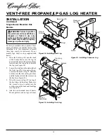
18", 24", and 30"
Variable Manually-
Controlled Models
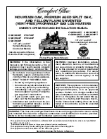
MOUNTAIN OAK, PREMIUM AGED SPLIT OAK,
AND YELLOW FLAME UNVENTED
(VENT-FREE) PROPANE/LP GAS LOG HEATERS
CGD3924PT
CGD3930PT
CGD3018PT
CGB3924PT
CGB3930PT
18", 24" and 30"
Thermostatically-Controlled
Models
(Also Designed Certified as
Vented Decorative Appliance)
®
Patent Pending
This appliance may be installed in an aftermarket* manufactured (mobile) home, where not prohibited
by state or local codes.
* Aftermarket: Completion of sale, not for purpose of resale, from the manufacturer
This appliance is only for use with type of gas indicated on the rating plate.
This appliance is not convertible for use with other gases.
(Yellow Flame Model Shown)


