background image

111739-01A

For more information, visit www.desatech.com

For more information, visit www.desatech.com

6

STOVE AND BURNER
SYSTEM ASSEMBLY

Continued

STOVE AND BURNER SYSTEM ASSEMBLY

Removing/Replacing Glass Door
Installing Optional Blower Accessory

REMOVING/REPLACING DOORS AND GLASS

You must remove doors and glass panel to install logs, lava rock, and
ember material. To remove glass panel, you must first remove the
door assembly on stove body.

 CAUTION: Do not operate this burner system with

a broken glass panel or without the door assembly
securely in place. For replacement part information
see 

Replacement Parts, page 33.

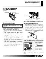
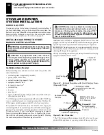
Figure 8 - Removing Glass Panel from Burner System

Figure 7 - Removing Door Assembly from Stove

1.

Lift middle grate and set aside (see Figure 7).

2.

Remove two bolts from bottom of stove using an adjustable
wrench or 10 mm socket and one bolt from the top of stove with
an M6 allen wrench to remove door assembly (see Figure 7).

3.

Remove the screws from the 2 tabs at the top of the glass panel
while holding door securely keeping it from falling forward.

4.

Grasp panel by both sides and ease it upward off of the lower
bracket (see Figure 8)

5.

To replace glass panel and door assembly, follow the above
instructions in reverse.

Bolt

Bolt

Door
Assembly

Middle
Grate

NOTICE: If installing blower in an existing stove
burner system with gas connections, shut off gas
supply and disconnect heater from gas supply. Con-
tact a qualified service person to do this.

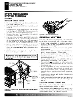
1.

Using an adjustable wrench or 10 mm socket, remove 4 hex
screws securing rear cover to back of stove body (see Figure 9).

2.

Separate bottom cover from rear cover by loosening the 8
mounting screws (see Figure 9).

3.

Align the holes in the top mounting tabs of blower with the
holes in wall of rear cover. Using the 4 screws provided, mount
blower and tighten screws securely (see Figure 10, page 7).

Figure 9 - Removing Rear Cover and Bottom Cover from Stove
Body

Stove Body

Rear Cover

Bottom Cover

Hex
Screws

Mounting
Screws

Mounting
Screws

Hex Screws

Mounting
Screws

Screw

Glass
Panel

INSTALLING OPTIONAL BLOWER
ACCESSORY

Summary of Contents for CSDBN

Page 1: ...OUR SAFETY Do not store or use gasoline or other flammable vapors and liquids in the vicinity of this or any other appliance Installation and service must be performed by a qualified installer service agency or the gas supplier IMPORTANT This direct vent burner system must be installed into approved Comfort Glow cast iron stove bodies models CSDBN ONLY This appliance may be installed in an afterma...

Page 2: ...ianStandardsAssociationtotheaboveteststandards Thisstove with burner system is a vented product This stove with burner system will not produce any gas leakage into your home if properly installed Thisstovewithburnersystemmustbeproperlyinstalledbyaqualified serviceperson Theglassdoormustbeproperlyseatedandsealed Ifthis unit is not properly installed by a qualified service person with glass door pro...

Page 3: ...or burn paper or other objects 13 Never place anything on top of stove 14 Do not use any solid fuels wood coal paper cardboard etc in this stove Use only the gas type indicated on burner system nameplate 15 This appliance when installed must be electrically grounded in accordance with local codes or in the absence of local codes with the National Electrical Code ANSI NFPA 70 or the Ca nadian Elect...

Page 4: ...r walls or cause odors LOCAL CODES Install and use stove and burner system with care Follow all local codes In the absence to local codes use the current National Fuel Gas Code ANSI Z223 1 NFPA 54 USA or the current CSA B149 1 or 2 Installation Codes Canada Available from American National Standards Institute Inc 1430 Broadway New York NY 10018 National Fire Protection Association Inc Batterymarch...

Page 5: ... enclo sure Two or more people must carefully lift stove up and out of wooden crate 3 Remove plastic bag from stove body 4 Remove bubble wrapped log set from stove Doors must be re movedtodothisstep SeeRemoving ReplacingDoorsandGlass page 6 Remove all protective packaging applied for shipment 5 Check all items for any shipping damage If damaged promptly inform dealer where you bought heater Some f...

Page 6: ...Remove the screws from the 2 tabs at the top of the glass panel while holding door securely keeping it from falling forward 4 Grasp panel by both sides and ease it upward off of the lower bracket see Figure 8 5 To replace glass panel and door assembly follow the above instructions in reverse Bolt Bolt Door Assembly Middle Grate NOTICE If installing blower in an existing stove burner system with ga...

Page 7: ...y installed to fit against back of fireplace insert af ter the rear cover assembly has been reinstalled Green Ground Wire Wiring Diagram Decal Speed Control Black Wire White Wire Blue Wire Power Cord Route Through Plastic Bushing in Bottom Cover When Assembled Screw Thermal Switch WARNING Never touch the blower wheel while in operation WARNING Failure to position the parts in accor dance with supp...

Page 8: ...ne LP Conversion Kit INSTALLING PROPANE LP CONVERSION KIT If your burner system is natural gas do not install conversion kit This kit is for users with propane LP gas only Burner Main Burner Orifice and Pilot Orifice Conversion 1 Front door assembly and glass panel must be removed before installing conversion kit See Removing Replacing Doors and Glass page 6 2 Locate gas line connections and gas c...

Page 9: ...ep 2 Tighten screws securely approximately 25 in lbs see Figure 17 STOVE AND BURNER SYSTEM ASSEMBLY Installing Propane LP Conversion Kit Cont LO H I P I L O T OFF ON Mounting Screws Phillips Head Regulator Assembly Rubber Gasket Gas Control Valve Figure17 Removing ReplacingRegulatorAssemblyandRubber Gasket Conversion Labeling and Placement 1 Apply the English and French conversion labels over the ...

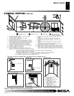
Page 10: ...tion area You must maintain minimum wall and ceiling clearances shown in Figures 3 and 4 page 5 If installing horizontal vent termination cap on an exterior wall with siding you must us a vinyl siding standoff see Figure 29 page 14 To Control Switch STOVE AND BURNER SYSTEM ASSEMBLY Continued STOVE AND BURNER SYSTEM ASSEMBLY Installing Rear Cover GENERAL VENTING Location of Vent Termination WARNING...

Page 11: ... supply inlet 72 inches 182 9cm minimum L clearance above paved side walk or a paved driveway located on public property 84 inches 213 3cm minimum M clearance under veranda porch deck 12 inches 30 5cm minimum N clearance above a roof shall extend a minimum of 24 inches 61cm above the highest point when it passes through the roof surface and any other obstruction within a horizontal distance of 18 ...

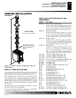
Page 12: ... cm from the top of the pipe and 1 2 54 cm minimum to the sides and bottom Vertical sections of this system require a minimum of 1 2 54 cm clearance to combustible materials on all sides of the pipe INSTALLATION PLANNING There are two basic types of direct vent installation Horizontal Termination Vertical Termination It is important to select the proper length of vent pipe for the type of terminat...

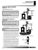
Page 13: ...ee Figure 26 Note Horizontal runs of vent must be supported every three feet Use wall straps for this purpose VENTING INSTALLATION Continued WARNING Do not recess vent terminal into a wall or siding Figure 24 Snorkel Termination Snorkel Figure 25 Snorkel Termination with Drainage Pipe 12 Minimum 30 5cm NOTICE Treatment of firestops and construction of the chase may vary from building type to build...

Page 14: ...te or other types of siding Combustible ExteriorWall For vinyl siding stucco or wood exteriors a siding standoff must be installed between the vent cap and exterior wall The siding standoff prevents excessive heat from damaging siding materials Siding materials must be cut to accommodate standoff Bolt the vent cap to the stand off Apply non hardening mastic around outside edge of the standoff Posi...

Page 15: ...izontal maximum dimensions which must be met Seal all connections with high temperature silicone sealant outer pipe only as specified in the second warning statement on page 12 All horizontal piping runs require 1 4 6 35 mm rise per 12 0 3 m of horizontal run Figure 32 Horizontal Termination Configuration for Venting Using Two 90 Elbows VENTING INSTALLATION Continued VENTING INSTALLATION Installat...

Page 16: ...s than three nails per side see Figure 35 2 Assemble the desired lengths of pipe and elbows necessary to reach from the burner system flue up through the firestop All connections must be sealed with high temperature sili cone sealant as specified in the second warning statement on page 12 Be sure all pipe and elbow connections are fully twist locked see Figure 26 page 13 3 Cut a hole in the roof u...

Page 17: ...seal outer pipe connection with high temperature silicone seal ant as specified in the second warning statement on page 12 Note Iftheventpipepassesthroughanyoccupiedareasabovethefirst floor includingstoragespacesandclosets youmustenclosepipe You may frame and sheetrock the enclosure with standard construction material Make sure and meet the minimum allowable clearances to combustibles Donotfillany...

Page 18: ...s shown Note Install restrictor into 4 10 16 cm collar of burner system as shown VENTING INSTALLATION Installation for Vertical Termination Cont Venting with Two 90 Elbows Vertical V Horizontal H1 Horizontal H2 5 min 1 52 m 2 max 0 61 m 6 min 1 83 m 4 max 1 22 m 7 min 2 13 m 6 max 1 83 m 8 min 2 44 m 8 max 2 44 m 20 max 6 1 m 8 max 2 44 m Venting with Two 90 Elbows Vertical V1 Horizontal H 5 min 1...

Page 19: ...rmination 90 Elbow 7 12 17 78 cm 0 3 m Adjustable Coaxial Pipe 6 15 24 cm Pipe Adaptor 4 1 22 m Coaxial Pipe Wall Firestop Decorative Trim Plate and 18 Screws VKS 47 K Snorkel Vent Kit Includes 36 0 91 m Snorkel Termination 90 Elbow 7 12 17 78 cm 0 3 m Adjustable Coaxial Pipe 6 15 24 cm Pipe Adaptor 4 1 22 m Coaxial Pipe Wall Firestop Decorative Trim Plate and 18 Screws VKR 47 K Roof Vent Kit Incl...

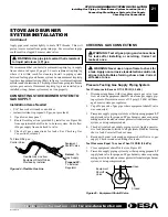
Page 20: ...ler must supply an external regulator The external regulator will reduce incoming gas pressure Youmustreduceincominggaspressuretobetween11and 14 inches of water If you do not reduce incoming gas pressure burner system regulator damage could occur Install external regu lator with the vent pointing down as shown in Figure 42 Pointing the vent down protects it from freezing rain or sleet WARNING A qu...

Page 21: ...ing Gas Supply Piping System Test Pressures In Excess Of 1 2 PSIG 3 5 kPa 1 Disconnect appliance with its appliance main gas valve con trol valve and equipment shutoff valve from gas supply pip ing systems Pressures in excess of 1 2 psig 3 5 kPa will dam age burner system gas regulator 2 Cap off open end of gas pipe where equipment shutoff valve was connected 3 Pressurize supply piping system by e...

Page 22: ...oncorrosive leak test solution to all gas joints Bubbles forming show a leak Correct all leaks at once Pressure Testing Burner System Gas Connections 1 Open equipment shutoff valve see Figure 45 page 21 2 Open propane LP supply tank valve for propane LP burner system or main gas valve located on or near gas meter for natu ral gas burner system 3 Make sure control knob of burner system is in the OF...

Page 23: ...om the back on each side of the base see Figure 49 WARNING Do not connect this thermostat to a power source Electrical shock and or fire hazard will occur Figure 49 Back View of Thermostat Base Feed wires through rectangular slots Figure 50 Thermostat Base Terminal W and R W R Terminal W Terminal R 7 Connect one bare wire end to each terminal W and R of the thermostat base see Figure 50 8 Install ...

Page 24: ... INSTALLING LOGS LAVA ROCK AND GLOWING EMBERS 1 2 Figure 55 Installing Log No 1 Figure 56 Installing Log No 2 You must remove glass door and front panel to install logs lava rock and ember material See Removing Replacing Glass Door page 6 STOVE AND BURNER SYSTEM INSTALLATION Continued Figure 53 Installing Battery in Hand Held Remote Control Unit GHRCB Series Installing 9 Volt Alkaline Battery in H...

Page 25: ...ructions exactly a fire or explosion may result causing prop erty damage personal injury or loss of life A This appliance has a pilot which must be lighted by hand When lighting the pilot follow these instructions exactly B BEFORE LIGHTING smell all around the appliance area for gas Be sure to smell next to the floor because some gas is heavier than air and will settle on the floor WHAT TO DO IF Y...

Page 26: ...ontrol knob all the way and hold Immedi ately light the pilot by repeatedly depressing the piezo spark ignitor until a flame appears Continue to hold for about one 1 minute after the pilot is lit Release gas control knob and it will pop back Pilot should remain lit If it goes out repeat steps 5 through 8 page 25 If gas control knob does not pop up when released stop and immediately call your servi...

Page 27: ...d remote in the AUTO mode close to the fireplace The radiant heat from the fireplace will turn off the fireplace Ideally place the hand held remote in the center of the room facing towards the fireplace Note Do not hold the hand held remote for a long time Body temperature will affect its operation in the AUTO mode Figure 62 On Off Hand Held Remote Control Unit GHRCB Control Button Turns Burners O...

Page 28: ...cally controlled blower has an ON setting and an OFF setting The blower will only run when the switch is in the ON position In the OFF position the blower will not operate If you are using CDA3620TB blower with optional thermostat wall mount or remote control for the burner system your burner system and blower will not turn on and off at the same time The burner system may run for several minutes ...

Page 29: ...mbers page 24 to properly replace logs Use a vacuum cleaner to remove any carbon buildup on logs Replace log s if broken See Replacement Parts on page 33 Replace ember material periodically as needed See Replacement Parts on page 33 VENTING SYSTEM Conduct annual inspection of the venting system following these guidelines 1 Check areas of venting system that are exposed to the weather for corrosion...

Page 30: ...e B Dirty or partially clogged pilot 5 Thermocouple connection loose at con trol valve 6 Thermocouple damaged 7 Control valve damaged REMEDY 1 Reconnect ignitor cable 2 Free ignitor cable if pinched by any metal or tubing Keep ignitor cable dry 3 Tighten nut holding piezo ignitor Nut is located behind the mounting bracket 4 Replace ignitor cable 5 Replace piezo ignitor 6 Replace pilot assembly 7 R...

Page 31: ...oved from line Have gas line checked by local pro pane LP or natural gas company 3 Clean burner see Cleaning and Maintenance page 29 or replace burner orifice 1 Adjust the log set so that the flame does not excessively impinge on it 2 Inspect the opening at the base of the burner to see that it is NOT packed with any type of material 3 Follow venting configuration instructions in owner s manual 1 ...

Page 32: ... valve defective 1 Gas leak See Warning statement above 1 Improper log placement 2 Air holes at burner inlet blocked 3 Burner flame holes blocked 4 Improper vent configuration OBSERVED PROBLEM Burner system produces unwanted odors Burner system shuts off in use Gas odor even when control knob is in OFF position Gas odor during combustion Dark residue on logs or inside of burner system REMEDY 1 Loc...

Page 33: ...lbs kg Stove and Crate 195 lbs 88 5 kg 195 lbs 88 5 kg Burner System 70 lbs 31 8 kg 70 lbs 31 8 kg Shipping 265 lbs 120 2 kg 265 lbs 120 2 kg When installed in a model CSDBN series cast iron stove body REPLACEMENT PARTS Note Use only original replacement parts This will protect your warranty coverage for parts replaced under warranty PARTS UNDER WARRANTY Contact authorized dealers of this product ...

Page 34: ...more information visit www desatech com 34 TPTH TPTH TP TP TH TH 24 4 19 20 21 23 26 1 26 4 26 2 26 3 18 24 4 25 4 1 28 28 4 7 8 9 10 11 13 12 15 16 17 22 4 2 3 6 22 27 23 14 4 5 ILLUSTRATED PARTS BREAKDOWN MODEL SDVBNC ILLUSTRATED PARTS BREAKDOWN Model SDVBNC ...

Page 35: ...7 01 Relief Spring 2 11 104528 01 Relief Washer 2 12 H5C4 20B Hex Head Cap Screw 2 13 NTC 4C Locknut 2 14 105468 02 Valve Bracket 1 15 14389 Valve Natural Gas 1 16 14561 Pilot Assembly Natural Gas 1 17 102445 01 Ignitor Piezo 1 18 11200 Screw 2 19 106036 01 Burner Natural Gas 1 20 104506 16 Orifice Natural Gas 1 21 14528 Brass Elbow 1 22 901056 01 Brass Elbow 2 23 101628 04 Flex Tubing 2 24 106794...

Page 36: ...ion visit www desatech com For more information visit www desatech com 36 ILLUSTRATED PARTS BREAKDOWN STOVE CHASSIS MODELS CSDBN AND CSDPBN ILLUSTRATED PARTS BREAKDOWN Models CSDBN and CSDPBN 5 6 3 5 5 5 3 4 7 6 1 6 2 5 2 1R 1C 1L ...

Page 37: ...op Grate Left 1 1C 111698 10 111698 24 Top Grate Center 1 1R 111698 04 111698 05 Top Grate Right 1 2 111698 11 111698 12 Bottom Door 1 3 111698 14 111698 15 Left Stove Door 1 4 111698 17 111698 18 Right Stove Door 1 5 111698 20 111698 21 Leg 4 6 111764 01 111764 01 Hardware Kit 1 6 1 Door Hinge Step Bolt With Shoulder 1 Per Unit With Two M8 Washers 1 6 2 Door Catch Bolt M8 x 1 25 55mm Long With Tw...

Page 38: ... you feel your gas pressure is too low contact your local natural or propane LP gas supplier TECHNICAL SERVICE You may have further questions about installation operation or troubleshooting If so contact DESA s Technical Service Depart mentat1 866 672 6040 Whencalling pleasehaveyourmodeland serial numbers of your heater ready You can also visit DESA s technical service web site at www desatech com...

Page 39: ...l Completed College Completed Graduate School 13 Age of Purchaser Under 20 20 29 30 39 40 49 50 59 60 or Over 14 Buyer s total annual household income Under 15 000 15 000 to 19 999 20 000 to 34 999 35 000 to 49 999 50 000 to 74 999 75 000 to 99 999 100 000 and Over 15 Store where product was purchased Name ______________________________________ City _______________________ State __________ 16 In c...

Page 40: ...111739 01A For more information visit www desatech com For more information visit www desatech com 40 2701 Industrial Drive P O Box 90004 Bowling Green KY 42102 9004 Postage Required TAPE TAPE ...

Page 41: ...____________________________________________________________ _______________________________________________________________________________________________ _______________________________________________________________________________________________ _______________________________________________________________________________________________ ___________________________________________________...

Page 42: ...ive stove and burner system will be the responsibility of the owner TO THE FULL EXTENT ALLOWED BY THE LAW OF THE JURISDICTION THAT GOVERNS THE SALE OF THE PRODUCT THIS EXPRESSWARRANTYEXCLUDESANYANDALLOTHEREXPRESSEDWARRANTIESANDLIMITSTHEDURATIONOFANYAND ALL IMPLIED WARRANTIES INCLUDING WARRANTIES OF MERCHANTABILITY AND FITNESS FOR A PARTICULAR PURPOSE TO TWO 2 YEARS ON ALL COMPONENTS FROM THE DATE ...

Reviews: