background image

104463-01E

For more information, visit www.desatech.com

For more information, visit www.desatech.com

9

9

INSTALLATION

Continued

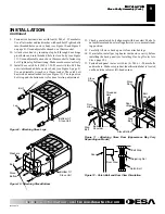
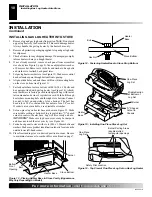
Figure 9 - Attaching Stove Legs

Bottom Of
Stove Unit

Leg

Bolt

Figure 10 - Attaching Stove Bottom

Bottom Of
Stove Unit

Bolt

Washers

Stove
Bottom

9.

Fasten stove bottom to stove with four (4) M6 x 1 - 25mm bolts.
Use a flat washer and lock washer with each bolt. Tighten bolts
into threaded holes on stove body (see Figure 10 and Figure 8
on page 8). Use an adjustable wrench or a 10mm socket.

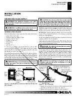
10. Attach stove door by inserting step bolt through door hinge

pivot holes and into threaded hole in stove body (see Figure
11). Use an adjustable wrench or a 12mm socket to fasten step
bolt. Tighten step bolt until snug. Make sure door moves freely.

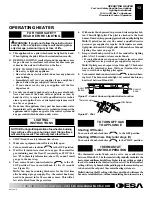
11. Install door catch bolt (M8 x 1.25-55mm with two M8 hex

nuts) into threaded hole on stove body (see Figure 8, page 8).
Use an adjustable wrench or a 12mm socket. The catch bolt
has two hex nuts attached to it (see Figure 12). The top nut is a
bolt stop and the bottom nut is for door leveling adjustment.

12. Check general catch bolt alignment with door claw. Make fi-

nal adjustment and door leveling after stove is in normal stand-
ing position.

13. Carefully lift stove back up on its four attached legs.

14. If available, install gas log heater inside stove cavity before

installing the back panel (see Installing Gas Log Heater Into
Stove,
 page 10).

15. Fasten back panel to stove with six (6) M6 x 1 - 20mm bolts

and washers. Make sure product identification label is located
on the outside in lower left-hand corner.

Figure 11 - Attaching Stove Door (Appearance May Vary
Depending on Model)

Step
Bolt

Door
Hinge

Threaded
Hole

Stove
Door

Stove Bottom

Bolt
Shoulder

Door
Hinge

Step
Bolt

Bolt
Shoulder

Stove
Door

Adjusting Nut

Bolt Stop

Catch Bolt

Door Claw

Door

Figure 12 - Catch Bolt and Door Claw Orientation

INSTALLATION

Stove Cavity Assembly (Cont.)

INSTALLATION

Stove Cavity Assembly (Cont.)

Summary of Contents for SL30NT Series

Page 1: ...ncy or the gas supplier WARNING This is an unvented gas fired heater It uses air oxygen from the room in which it is installed Provisions for adequate combustion and ventilation air must be pro vided...

Page 2: ...id any drafts that alter burner flame patterns Ceiling fans can create drafts that alter burner flame patterns Altered burner patterns can cause sooting WARNING Do not use a blower insert heat exchang...

Page 3: ...n burner box or on adjacent walls or furniture 10 This heater needs fresh outside air ventilation to run properly This heater has an Oxygen Depletion Sensing ODS safety shutoff system The ODS shuts do...

Page 4: ...orless passageways or ventilation grills between them WARNING This heater shall not be installed in a confined space or unusually tight construction unless provisions are provided for adequate com bus...

Page 5: ...ent gas appliances Direct vent draws combustion air from the outdoors and vents to the outdoors Example Gas water heater 40 000 Btu Hr Vent free heater 30 000 Btu Hr Total 70 000 Btu Hr WARNING If the...

Page 6: ...unconfined space When ventilating to an adjoining unconfined space you must provide two permanent openings one within 12 of the ceiling and one within 12 of the floor on the wall connecting the two s...

Page 7: ...from floor ceil ing and adjoining side and back walls Carefully follow the instructions below This stove is a freestanding unit designed to set directly on the floor IMPORTANT You must maintain minimu...

Page 8: ...include 1 Stove bottom 4 Legs 1 Bottom door 1 Top grate 1 Hardware kit bag with fasteners 6 Carefully lay stove body on back to attach bottom components to stove body see Figure 6 Rest stove on drop...

Page 9: ...8 page 8 Use an adjustable wrench or a 12mm socket The catch bolt has two hex nuts attached to it see Figure 12 The top nut is a bolt stop and the bottom nut is for door leveling adjustment 12 Check g...

Page 10: ...rough stove bottom Connect hex nut to bolt on underside of stove bottom The bolt hex head is for a 5 16 socket and the hex nuts are for a 3 8 socket If sockets are not available use adjustable wrenche...

Page 11: ...Purchase the optional CSA design certified equipment shutoff valve from your dealer See Accessories page 19 The gas inlet connection for the stove heater is located on the lower right hand side of the...

Page 12: ...ct all leaks at once 6 Reconnect heater and equipment shutoff valve to gas supply Check reconnected fittings for leaks Test Pressures Equal To or Less Than 1 2 PSIG 3 5 kPa 1 Close equipment shutoff v...

Page 13: ...cluding near the floor If you smell gas STOP Fol low B in the safety information above If you don t smell gas go to the next step 5 Turn control knob counterclockwise C clockwise to the PI LOT positio...

Page 14: ...aning easier 1 Shut off the unit including the pilot Allow the unit to cool for at least thirty minutes 2 Inspect burner pilot and primary air inlet holes on injector holder for dust and dirt see Figu...

Page 15: ...ND MAINTENANCE Continued CLEANING AND MAINTENANCE Logs Main Burner SPECIFICATIONS 4 Check the injector holder located at the end of the burner tube again Remove any large particles of dust dirt lint o...

Page 16: ...trol valve 6 Thermocouple damaged 7 Control valve damaged REMEDY 1 Reconnect ignitor cable 2 Free ignitor cable if pinched by any metal or tubing Keep ignitor cable dry 3 Replace ignitor cable 4 Repl...

Page 17: ...d let warm up for a minute 2 Operate burner until air is removed from line Have gas line checked by local natural gas company 3 Observe minimum installation clear ances see page 7 4 Clean burner see C...

Page 18: ...s a clicking ticking noise just after burner is lit or shut off Heater produces unwanted odors Heater shuts off in use ODS operates Gas odor even when control knob is in OFF position Gas odor during c...

Page 19: ...ur model and serial numbers of your heater ready You can also visit DESA International s technical service web site at www desatech com SERVICE HINTS When Gas Pressure Is Too Low pilot will not stay l...

Page 20: ...r more information visit www desatech com For more information visit www desatech com 20 ILLUSTRATED PARTS BREAKDOWN SL30NT 14 16 3 4 15 5 11 6 12 7 10 15 8 9 1 17 2 18 18 18 13 ILLUSTRATED PARTS BREA...

Page 21: ...Gas Regulator 1 6 104425 01 Inlet Tube 1 7 104424 01 Outlet Burner Tube 1 8 099056 26 Burner Orifice Injector 1 9 111124 01 Burner Retainer Spring 1 10 102980 01 Burner 1 11 101329 21 Control Valve 1...

Page 22: ...For more information visit www desatech com For more information visit www desatech com 22 ILLUSTRATED PARTS BREAKDOWN CISC CISG 7 4 6 4 5 4 5 1 5 2 3 5 3 5 4 2 1R 1C 1L ILLUSTRATED PARTS BREAKDOWN CI...

Page 23: ...een 1 3 104174 03 Stove Dropped Bottom 1 4 104970 01 One Leg Charcoal 4 Total Per Stove 1 104970 02 One Leg Forest Green 4 Total Per Stove 1 5 104971 01 Hardware Kit 1 5 1 Door Hinge Step Bolt With Sh...

Page 24: ...9 Adams Street Bowling Green KY 42103 3414 270 846 1199 1 800 654 8534 Fax 1 800 846 0090 franktalk aol com Master Parts Dist 1251 Mound Ave NW Grand Rapids MI 49504 2672 616 791 0505 1 800 446 1446 F...

Page 25: ...Completed College Completed Graduate School 13 Age of Purchaser Under 20 20 29 30 39 40 49 50 59 60 or Over 14 Buyer s total annual household income Under 15 000 15 000 to 19 999 20 000 to 34 999 35 0...

Page 26: ...104463 01E For more information visit www desatech com For more information visit www desatech com 26 2701 Industrial Drive P O Box 90004 Bowling Green KY 42102 9004 TM Postage Required TAPE TAPE...

Page 27: ...________________________________________________________ _______________________________________________________________________________________________ _______________________________________________...

Page 28: ...ement parts voids this warranty The heater MUST be installed by a qualified installer in accordance with all local codes and instructions furnished with the unit This warranty does not apply to parts...

Reviews: