3
3
CZHVP30CN
www.comfortzoneproducts.com
NOTE:
This fan is equipped with thermal cutoff switch. If fan
overheats for any reason, this switch will stop the fan. The switch
will reset automatically after the fan cools.
Operating Instructions:
Plug power cord into any properly grounded, 3‑prong, 120 volt
wall outlet. The fan speed is controlled by a 3‑speed rotary
switch. Turn the rotary switch to change the speed or turn the
fan off. Height of fan can be adjusted by loosening cap screw
(19). Make sure collar is tight before operating fan. The angle
can be adjusted by loosening the knob screw (16) which holds
the motor to the column. Once you have the desired angle, be
sure to tighten the knob screw. Do not attempt to relocate fan by
dragging the base. The fan can be moved to its next location by
tilting it on the edge of the base and rolling it, or by carrying it.
Assembly Instructions
Tools Required:
Phillips Screwdriver and Adjustable Wrench.
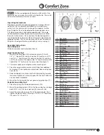
Head Assembly Fig 1
1. Mount motor assembly (9) to extension column (14) with
1/2" x 1" hex bolt (15) one lock washer (10) and hex nut (11)
and 1/4" x 1" knob screw (16) one lock washer (13) and hex
nut (12). Ensure that the knob on the 1/4" knob screw and the
head of the 1/2" bolt are on the same side. (See figure 1)
2. Tilt motor slightly up and tighten motor mounting nut.
3. Place the rear guard (8) on motor studs. Place four additional
flat washers (7), over grille onto motor studs. Secure using four
hex nuts (5).
4. Slide fan blade (4) on motor shaft with hub pointing towards
the motor. Tighten set screw (3) against flat on shaft with 5/32
hex key wrench provided.
5. Mount the front guard to the rear guard using grille clips (17).
Pedestal Assembly Fig 2
1. Place the spring (30) inside painted column (22).
2. Mount the painted column (22) to the base using four carriage
bolts 5/16" x 3/4" (23) lock washers (25) and nuts (26).
3. Adjust the extension column (14) to the proper height, then
tighten the plastic collar (18) using a 1/4‑20 x 1/4" cap screw
(19) and a 1/4"‑20 nut (12).
Fig 1
#
Description
Qty
1
Nameplate
1
2
Front Guard
1
3
Set Screw
5/16"‑ 24 x .250
1
4
Fan Blade
1
5
Nut #8‑32
4
6
Dome Cover
1
7
Flat Washer #10
4
8
Rear Guard
1
9
Motor
1
10 Lock Washer 1/2"
2
11 Nut 1/2"‑13
2
12 Nut 1/4"‑20
2
13 Lock Washer 1/4"
1
14 Extension Column
1
15 Bolt 1/2" – 13 x 1
1
16
Knob Screw
1/4" – 20 x 1"
1
17 Grille Clip
6
18 Collar
1
19
Cap Screw
1/4 ‑ 20 x 1‑1/4"
1
20
Power Cord
9ft/274cm
1
21 Screw #8 – 32 x 1/4"
1
22 Painted Column
1
23
Carriage Bolt
5/16" – 18 x .750
5
24 Base Plate
1
25 Lock Washer 5/16"
4
26 Nut 5/16" – 18
5
27 Rotary Switch
1
28 Plastic Spacer
1
29 Screw #8 – 18 x 5/16"
2
30 Spring
1
Fig 2
30


