


|
EN
22
1
10
9
7
8
6
5
4
2
3
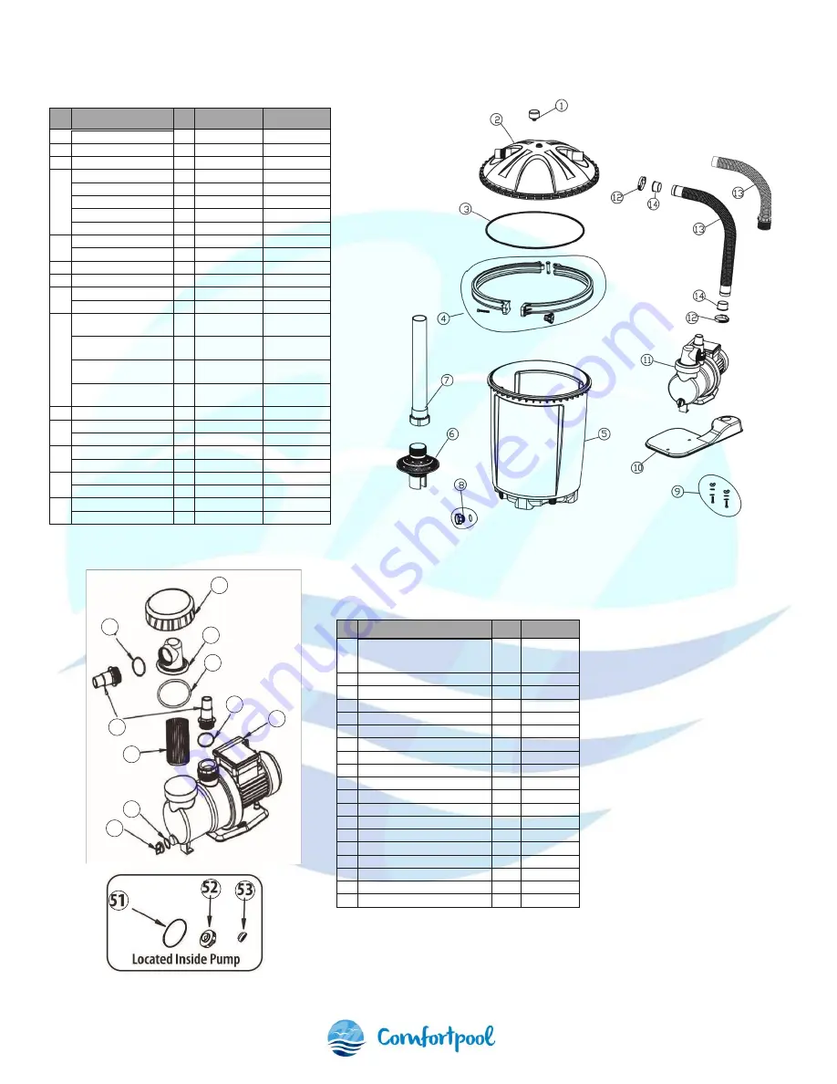
8. Parts
No. Part
Qty Part no.
For model
1
Pressure gauge
1
17001
7000 & 9500
2
Filter cover
1
17003
7000 & 9500
3
O-ring
1
17004
7000 & 9500
4
Left clamp ring
1
L00169
7000 & 9500
Right clamp ring
1
L00170
7000 & 9500
Clamp pin
1
L00171
7000 & 9500
M8*80 bolt
1
L00172
7000 & 9500
Plastic nut
1
L00173
7000 & 9500
5
Filter tank
1
1701025
7000
Filter tank
1
1701050
9000
6
Basket filter
1
17011
7000 & 9500
7
Hard tube
1
17012
7000 & 9500
8
Drain valve
1
17013
7000 & 9500
O-ring
1
17014
7000 & 9500
9
Pump bolt wing nut
PUMP MOUNTING
2
P00175
7000 & 9500
Pump bolt flat water
PUMP MOUNTING
2
P00176
7000 & 9500
Pump bolt lock washer
PUMP MOUNTING
2
P00177
7000 & 9500
Pump bolt nut
PUMP MOUNTING
2
P00178
7000 & 9500
10 Base plate
1
17019
7000 & 9500
11
Water pump 1/2hp
1
SPS1A450
7000
Water pump 3/4hp
1
SPS1A550
9000
12
Hose clamp
1
17021
7000
Hose clamp
2
17021
9000
13
Soft hose
1
1702225
7000
Soft hose
1
1702250
9000
14
Hose reducer
1
17023
7000
Hose reducer
2
17023
9000
No.
Part
Qty
Partno.
1
Water pump/ motor
1
SPS1A250
SPS1A450
SPS1A550
2
Transparent hair & lint strainer
1
P00131
3
11/4"- 1 1/2" hose connector
2
P00132
4
O-ring "A"- 2 1/4"
1
P00182
5
O-ring "B"- 3"
1
P00183
6
O-ring "C"- 1.5"
1
P00184
7
Strainer collar
1
P00133
8
Strainer basket
1
P00134
9
Pump drain cap
1
P00135
10
Drain valve O-ring
1
P00136
11
Motor pump seal
1
P00137
11
Motor pump seal
1
P00138
11
Motor pump seal
1
P00138
12
Impeller assembly
1
P00139
12
Impeller assembly
1
P00140
12
Impeller assembly
1
P00140
13
Shaft seal & spring assembly
1
P00141
13
Shaft seal & spring assembly
1
P00142
13
Shaft seal & spring assembly
1
P00142
Summary of Contents for FuzzyClean 7000
Page 1: ...FuzzyClean 7000 9500...
Page 10: ...NL 10 7 Installatie illustraties...


