User Manual for RGBHV/Stereo-Audio Matrix COMM-TEC MTX Series
COMM-TEC GMBH
www.comm-tec.de
6 of 10
3.4
RS-232 Connection
All functions of the MTX units can be controlled with external controllers like computers or third party controllers
(e.g. AMX). A serial controller is any device that is connected to the standard RS-232 serial port (9pin SubD
female) on the rear panel and that can send and receive ASCII character format.
The port settings are:
Connect serial controllers refering to the table below for RS-232 cable connector pin mapping:
4. Operation
The RGBHV matrix switcher can be controlled by the front control panel, infrared remote controller, Ethernet
control (optional), and the RS-232 communication port.
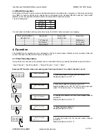
4.1 Front Panel Operation
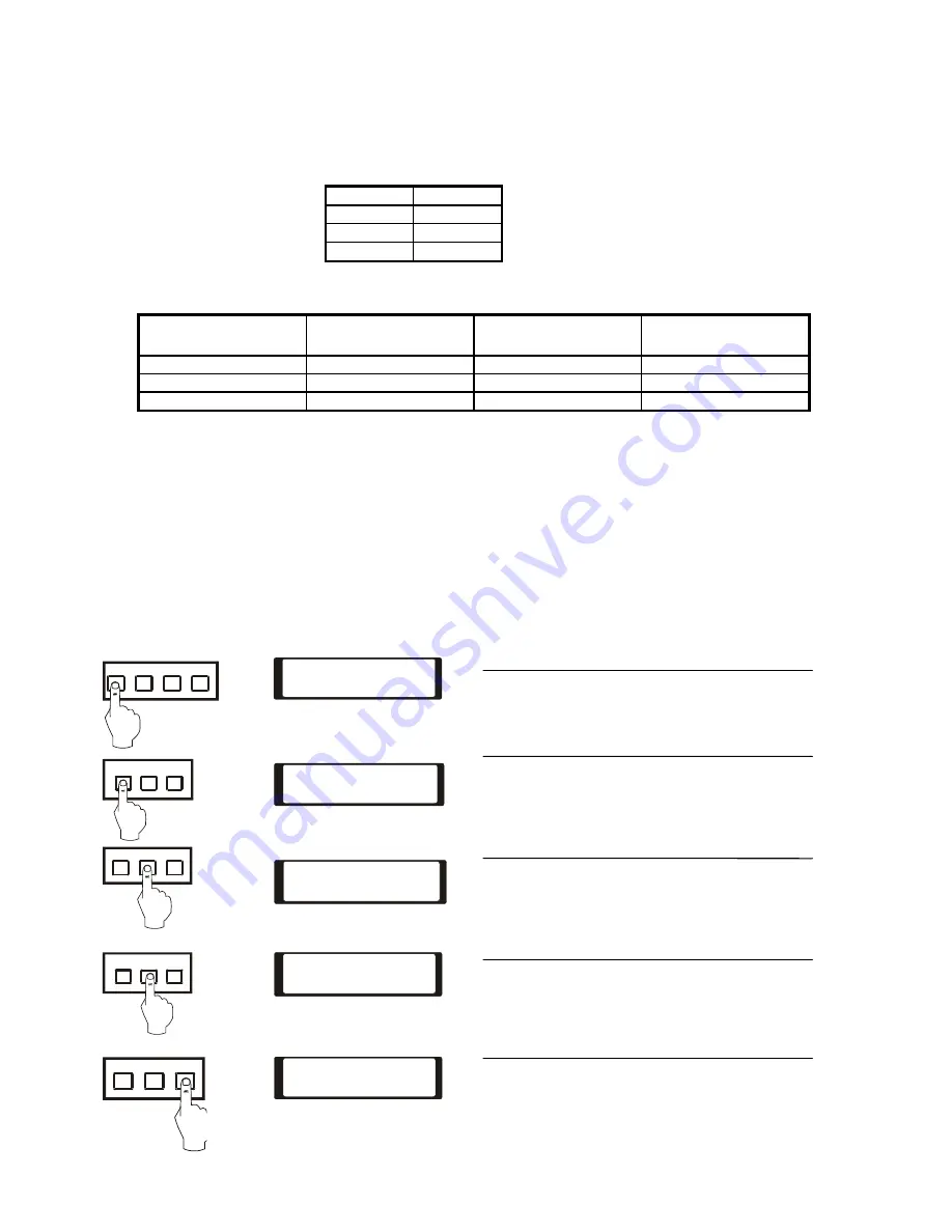
Using the front control panel, the switcher can be controlled directly by pressing the buttons using this format:
“Input Channel” + “Switching Mode” + “Output Channel” + “End” + “Enter”
Example 1
:
Transfer video and audio signals from input channel 1 to output channels 3 and 4
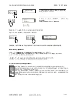
1. Press the button for input channel number “1”.
Display feedback on LCD: “1”
2. Press the button for switching mode “AV”.
Display feedback on LCD: “B” (“B” for both audio and
video, “A” for audio only; “V” for video only).
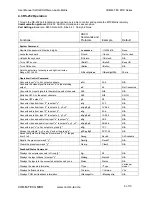
3. Press the button for the first output channel
number”3”.
Display feedback on LCD: “3”
4. Press the break button “/”.
Display feedback on LCD: “,”
5. Press the button for the second output channel
number “4”.
Display feedback on LCD: “4”
Pin-#. at UP-1280SU
RS-232 Port
Description
Pin-# at PC
RS-232 Port
Description
2
Tx Transmit
2
Rx Receive
3
Rx Receive
3
Tx Transmit
5
Gnd Ground
5
Gnd Ground
BAUD
9600
Data Bits
8
Stop Bit
1
Parity
NONE
1
3
4
2
AV
Audio
Video
3
4
2
0
END
/
3
4
2
Input Command
:
1
Input Command
:
1B
Input Command
:
1B3
Input Command
:
1B3
,
Input Command
:
1B3 4
,


