background image

i

nsTallaTion

 i

nsTrucTions


U S   C U S T O M E R   S U P P O R T 1 - 8 8 8 - 6 2 2 - 2 3 7 7   |   W W W. C O M M A N D A C C E S S . C O M   |   C A  C U S T O M E R   S U P P O R T   1 - 8 5 5 - 8 2 3 - 3 0 0 2

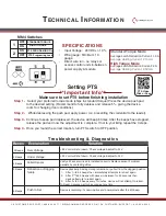
Note: For AHT4/5 & PD11’s purchased after 2015 only. 

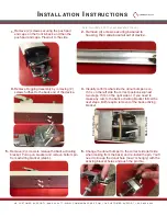
Remove (2) screws securing the push pad 

end caps on the front & back, and then the 

push pad end caps. Place all to the side

1.

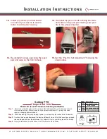
Remove Dogging Assembly by removing (2) 

screws furthest to the back end of the device.

3.

Remove (4) screws securing baserail to 

housing, then slide baserail out of device.

2.

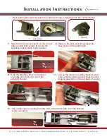
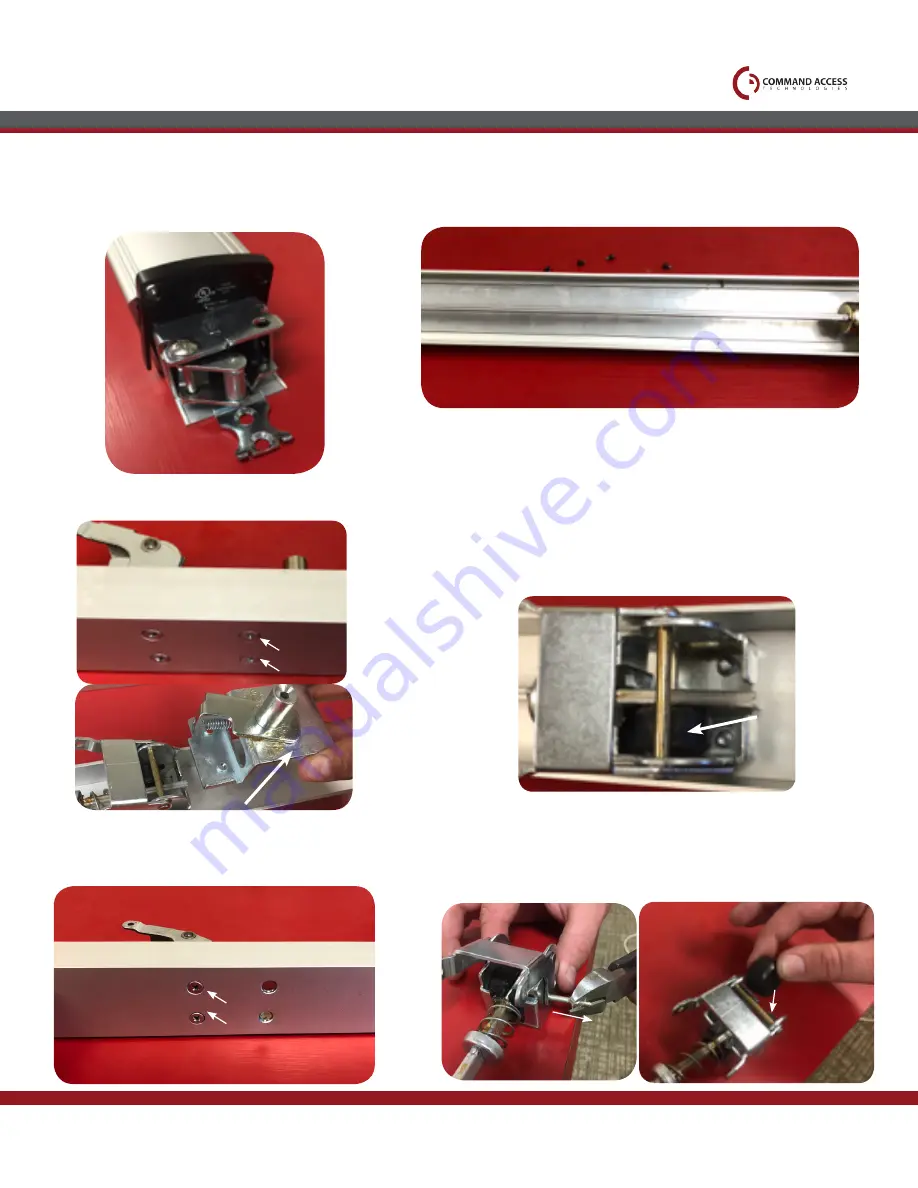
Visually confirm what side the donut bumper is on. 

If it is on the left side the correct position,skip next 

two steps. If it’s on the right side or  if you need to 

make any cuts to the back activiting bracket follow the 

next steps. Both require removal of the back activing 

bracket.

4.

1

2

Remove (2) screws to release the back activating 

bracket. Pull up on bracket and remove bottom pin 

from activiting bracket (step 6).

5.

1

2

Correct

Front of Device

Back of Device

Change the donut bumper to the correct side (left side 

when looking from the back) and re-install the pin. You’ll 

need to line up the donut hole (now I’m hungry) with the 

activing bracket holes and push the pin thru.

6.

Summary of Contents for PD10-UL-M-KIT

Page 1: ...phillips screws C o m m a n d A c c e s s Te c h n o l o g i e s 2 2 9 0 1 L a P a l m a A v e Yo r b a L i n d a C A 9 2 8 8 7 P h o n e 8 8 8 6 2 2 2 3 7 7 PD10 UL M KIT INSERT INSTRUCTIONS The PD10 UL M KIT is a field installable motorized latch pullback for the PD10 11 Doromatic or Falcon 1690 1790 First Choice 3600 3700 C A B 20410_B ...

Page 2: ...A Average Holding Current 250 mA High Torque Mode Average Latch Retraction Current 1 3 A Average Holding Current 215 mA Standard Torque Mode MM4 Switches ON ON OFF STANDARDTORQUE HIGH TORQUE PTS Programing Lock PTS PROGRAMING On OFF Input Voltage 24VDC 10 Wire gauge Minimum 18 gauge Direct wire run no relays or access control units in between power supply module 1 2 2 Beeps 3 Beeps 5 Beeps 6 Beeps...

Page 3: ...wer Supplies All Command Access exit devices field installable kits have been thoroughly cycle tested with Command Access power supplies at our factory For more information visit our website Electrified Exit Device Installation Example U S C U S T O M E R S U P P O R T 1 8 8 8 6 2 2 2 3 7 7 W W W C O M M A N D A C C E S S C O M C A C U S T O M E R S U P P O R T 1 8 5 5 8 2 3 3 0 0 2 ...

Page 4: ...serail out of device 2 Visually confirm what side the donut bumper is on If it is on the left side the correct position skip next two steps If it s on the right side or if you need to make any cuts to the back activiting bracket follow the next steps Both require removal of the back activing bracket 4 1 2 Remove 2 screws to release the back activating bracket Pull up on bracket and remove bottom p...

Page 5: ... side re install both screws to secure the activating bracket back to the baserail 7 Depress the back activating bracket for easy access to the bottom pin 8 11 Line up the motor s mounting bracket screw holes with the existing screw holes from the dogging assembly on the exit device housing Cut down Good 3 4 Cut Back Activing Bracket will need to be cutdown if it has a dogging hook like pictured b...

Page 6: ...tches ON ON OFF STANDARDTORQUE HIGH TORQUE PTS Programing Lock PTS PROGRAMING On OFF 1 2 Select your preferred torque mode ships in standard torque Press the device push pad to the desired setting Recommend to fully depress and release 5 giving the device room for changing door conditions Step 2 While depressing the push pad apply power i e presenting the credential to the reader Step 3 Continue t...

Reviews: