8
1) Input 2 wire (IN01, IN02 ... IN16) shall be connected at a switch.
2) Output 2 wire shall be connected at each functional switch, if each input will be
functional, the related output will be lighted.
8.7 Inductor Connection
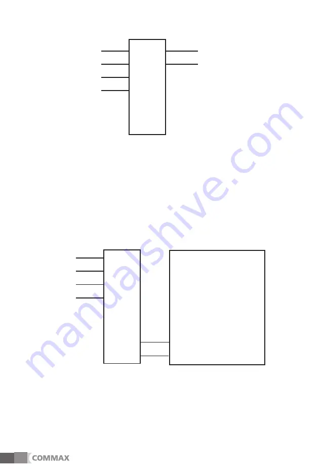
The inductor shall be connected as the following schematic.
(Refer to the drawing no. 9-4)
4 WIRE
IIN
ND
DU
UC
CT
TO
OR
R
DC 24V(+)
4WIRE OUT
4 Wire
IN 2 Wire
www.safemag.ru
www.safemag.ru


