background image

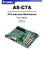
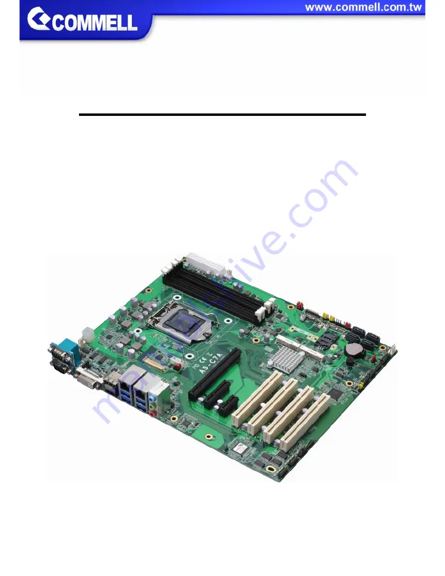
AS-C7A

ATX Industrial Motherboard

User’s Manual

Edition 1.4

2017/01/20

Summary of Contents for AS-C7A

Page 1: ...AS C7A ATX Industrial Motherboard User s Manual Edition 1 4 2017 01 20...

Page 2: ...ent are property of their respective owners Disclaimer The company shall not be liable for any incidental or consequential damages resulting from the performance or use of this product The company doe...

Page 3: ...ers Driver CD Including User s Manual x 1 1 x AS C7A ATX Industrial Motherboard 2 x SATA Cable OALSATA3 L 1040529 1 x VGA Cable OALVGA S 7 1040556 1 x Dual COM PORT Cable OALES BKU2 1040087 1 x USB3 0...

Page 4: ...S and Power on type selection 12 2 4 I O interface 12 2 4 1 Serial ATA interface 12 2 4 2 Ethernet interface 13 2 4 3 Display interface 13 2 4 4 Serial Port interface 16 2 4 5 USB interface 18 2 4 6 A...

Page 5: ...maximum supported is up to 64GB of DDR4 better performance flexibility and more enhanced security that is suitable for a variety of intelligent systems the ideal choice All in One multimedia solution...

Page 6: ...integrated HD Graphics Some Xeon E3 1200 v5 Product CPU not support Display Interface 1 x DVI I 1 x DisplayPort 2nd VGA optional 1 x LVDS 1 x HDMI 1 x VGA LAN Chip 1 x Intel I219 LM Gigabit PHY LAN Su...

Page 7: ...o PCIe x1 SATA3 LPC 1 x LPC ALC262 1 x SMBUS MiniPCIe mSATA SMBus 1 x CRT 1 x HDMI DDI DDI Channel A1 DDR4 DIMM 1 2V Channel A2 MiniPCIe mSATA SIO NCT6106D 5 x RS232 1 x RS232 RS422 RS485 1 x GPIO 1 x...

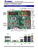
Page 8: ...S2 JFRNT I219 LM COM2 CN_CRT I210 AT COM1 DVI I HDMI Display Port AUDIO USB3 0 USB3 0 CN_USB2 2 CN_USB2 1 CN_COM3 4 CN_COM5 6 CN_DIO SATA3 2 SATA3 3 SATA3 4 CN _INV CPUFAN CN_12V ATX CN_USB 3 1 DDR4_A...

Page 9: ...IO 6 x 2 pin digital I O connector CN_CRT 16 pin VGA connector CPUFAN 4 pin CPU fan connector SYSFAN 4 pin system fan connector AUXFAN 4 pin system fan connector JFRNT 14 pin front panel switch indica...

Page 10: ...roperly Attention If AS C7A need RMA please Keep CPU socket cover on the CPU Socket Warning If CPU Socket internal Pin damage We could not provide warranty 1 Lift this bar 2 Uncover this plate Intel S...

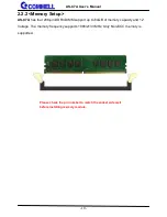
Page 11: ...has four 288 pin DDR4 DIMM support up to 64GB of memory capacity and 1 2 Voltage The memory frequency supports 1866 2133 MHz Only Non ECC memory is supported Please check the pin number to match the...

Page 12: ...Setting JMSATA1 MiniCard 1 MSATA Setting JMSATA2 MiniCard 2 MSATA Setting JP1 COM1 Voltage Setting For Pin 9 JP2 COM2 Voltage Setting For Pin 9 JCSEL1 COM2 RS 232 RS422 RS485 Setting JCSEL2 COM2 RS 2...

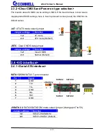
Page 13: ...per JRTC Clear CMOS data jumper Jumper settings Function 1 2 Clear CMOS 2 3 Normal Default 2 4 I O interface 2 4 1 Serial ATA interface SATA 1 2 3 4 SATA3 7 pin connector JVSATA3 2 SATA3 SATADOM mode...

Page 14: ...interface Based on the 6th Gen CPU with built in HD Graphics 530 VGA and DVI up to 1920x1080 60Hz DisplayPort up to 4096x2304 60Hz HDMI up to 4096x2304 24Hz on rear IO About the internal Display LVDS...

Page 15: ...10 IOGND1 11 NC 12 5VCDA 13 5HSYNC 14 5VSYNC 15 5VCLK 16 NC CN_LVDS LVDS 40 pin connector Model HIROSE DF13 40DP 1 25V compatible Pin Signal Pin Signal 2 Set by JVLCD 1 Set by JVLCD 4 Detect Active lo...

Page 16: ...8 GND 27 GND 30 A_LVDS_3 29 B_LVDS_CLK 32 A_LVDS_3 31 B_LVDS_CLK 34 GND 33 GND 36 LVDS_DDCSCL 35 NC 38 LVDS_DDCSDA 37 NC 40 NC 39 NC Pin4 only need to be connected to GND CN_INV LVDS 5 pin Backlight p...

Page 17: ...ial Port interface COM1 RS232 DB9 connector Pin Signal Pin Signal 1 DCD 2 RXD 3 TXD 4 DTR 5 GND 6 DSR 7 RTS 8 CTS 9 Set by JP1 COM2 COM1 1 2 19 20 CN_COM3 4 CN_COM5 6 1 2 19 20 JP2 6 1 5 2 12 1 11 2 J...

Page 18: ...XD1 3 TXD1 4 DTR1 5 GND 6 DSR1 7 RTS1 8 CTS1 9 RI1 10 NC 11 DCD2 12 RXD2 13 TXD2 14 DTR2 15 GND 16 DSR2 17 RTS2 18 CTS2 19 RI2 20 Key COM5 6 COM 20 pin header Pitch 2 54 x 1 27mm Pin Signal Pin Signal...

Page 19: ...ure COM2 communication mode Function JCSEL1 JCSEL2 RS232 Default RS485 RS422 2 4 5 USB interface 2 9 10 1 USB3 0 LEFT 12 1 11 2 5 1 6 2 5 1 6 2 12 1 11 2 USB3 0 RIGHT CN_USB3 1 1 10 11 20 CN_USB2 1 1...

Page 20: ...1 VCC 5V_SB 5V 20 NC 2 USB3 0_RX0 19 VCC 5V_SB 5V 3 USB3 0_RX0 18 USB3 0_RX1 4 Ground 17 USB3 0_RX1 5 USB3 0_TX0 16 Ground 6 USB3 0_TX0 15 USB3 0_TX1 7 Ground 14 USB3 0_TX1 8 Data0 13 Ground 9 Data0...

Page 21: ...ey 9 FP_OUT_L 10 FP_OUT_DETECT 2 4 7 Expansion slot MINI_CARD1 and MINI_CARD2 have some special design to compatible our mini PCIe card ex MPX 574D2 MPX 210D2 etc MINI_CARD1 support mSATA by JMSATA1 M...

Page 22: ...rt mSATA 2 3 Normal operation Default 2 4 8 Front panel switch and indicator JFRNT Front panel switch and indicator 14 pin header Pitch 2 54mm Pin Signal Pin Signal 1 HDD_LED 2 Power_LED 3 HDD_LED 4 N...

Page 23: ...not may cause damage As Input TTL level GPIO DC characteristics Parameter SYM MIN TYP MAX UNIT Conditions Input Low Voltage VIL 0 8 V Input High Voltage VIH 2 0 V Output Low Voltage VOL 0 4 V IOL 12m...

Page 24: ...2V CN_LPC LPC 12 pin header Pitch 2 00mm Pin Signal Pin Signal 1 CLK 2 RST 3 LFRAME 4 LAD3 5 LAD2 6 LAD1 7 LAD0 8 3 3V 9 SERIRQ 10 GND 11 3 3VSB 12 NC CN_PS 2 PS 2 10 pin header Pitch 2 54mm Pin Signa...

Page 25: ...YSFAN System cooler fan 4 pin connector Pin 1 2 3 4 Signal GND 12V Sensor Control AUXFAN AUX cooler fan 4 pin connector Pin 1 2 3 4 Signal GND 12V Sensor Control 2 5 Power supply 2 5 1 Power input CN_...

Page 26: ...TX main power 24 pin connector As input Pin Signal Pin Signal 1 3 3V 13 3 3V 2 3 3V 14 NC 3 GND 15 GND 4 5V 16 PSON 5 GND 17 GND 6 5V 18 GND 7 GND 19 GND 8 Power_OK 20 NC 9 5VSB 21 5V 10 12V 22 5V 11...

Page 27: ...e UFD which can boot into DOS enviroment 2 Unzip the flash tool and copy it into bootable UFD 3 Add a bin file to the same folder 4 Power on the system and flash the BIOS under the DOS environment Com...

Page 28: ...Dual channel NO Type NO Type 1 VBIOS DEFAULT 9 1366 x 768 2 640 x 480 10 1680 x 1050 3 800 x 600 11 1920 x 1200 4 1024 x 768 12 1400 x 900 5 1280 x 1024 13 1600 x 900 6 1400 x 1050 Reduced Blanking 1...

Page 29: ...program You can select Timer setting in the BIOS after setting the time options the system will reset according to the period of your selection Find the setting from Advanced Intel Advanced Menu Super...

Page 30: ...01h Timeout occurs after 1 minute only 02h Timeout occurs after 2 second minute 03h Timeout occurs after 3 second minute FFh Timeout occurs after 255 second minute The deviation is approx 1 second Fo...

Page 31: ...nter configuration o 4E 87 o 4E 07 o 4F 07 select Logical Device o 4E 30 o 4F 10 activate GPIO function The board use GPIO3 o 4E F0 o 4F XX set 01 GPIO as input set 00 GPIO as output o 4E F1 o 4F XX i...

Page 32: ...PCH IO Configuration SATA Configuration SATA Mode Selection If this screen stop time is too short it can be set in the BIOS Advanced Intel Advanced Menu PCH IO Configuration SATA Configuration Softwar...

Page 33: ...n help you please don t hesitate to contact with us We will do our best to support you for your products projects and business Taiwan Commate computer Inc Address 19F NO 94 Sec 1 Xintai 5 th Rd Xizhi...

Reviews: