background image

CMB-B72 

User’s Manual


-31- 

Appendix A <Install Desk/Wall mount>                                                                                     


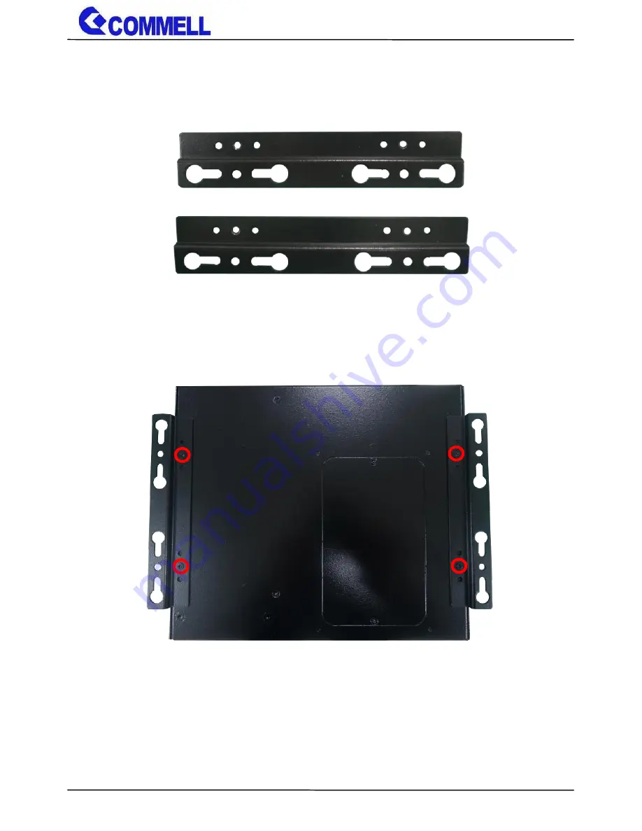
(a.) Screw on the rack mount as the picture below. 


Summary of Contents for CMB-B72

Page 1: ...CMB B72 Barebone system Intel High Performance Platform Installation Guide Edition 1 01 2017 01 20...

Page 2: ...ment are property of their respective owners Disclaimer The company shall not be liable for any incidental or consequential damages resulting from the performance or use of this product The company do...

Page 3: ...1 Including Motherboard and Backplane CD Driver x 1 Desk Wall mount x 1 pair 1 x PS 2 Keyboard Mouse Cable OALPS2 MKN 1040551 1 x USB3 0 Cable OALUSB3D 1040631 1 x USB2 0 Cable OALUSB27S 1040261 1 x...

Page 4: ...O interface 9 2 3 1 Serial ATA interface 9 2 3 2 Ethernet interface 10 2 3 3 Display interface 10 2 3 4 Serial Port interface 12 2 3 5 USB interface 14 2 3 7 Expansion slot 16 2 3 8 Front panel switch...

Page 5: ...lake H Processor with Intel QM170 Chipset PCH H The 6 th Generation Intel Core H series processor family is new generation and multi core processor built on 14 nanometer process provide new HD Graphic...

Page 6: ...PCI slot Graphics Chipset Intel 9th Gen integrated HD Graphics Display Interface 1 x DP 1 x DVI D optional for 2 x DVI D 1 x VGA LAN Chip 1 x Intel I219 LM Gigabit PHY LAN Support iAMT11 0 1 x Intel...

Page 7: ...Manual 6 Chapter 2 Product Specification 2 1 Motherboard Placement SATA3 3 SATA3 1 JFRNT I219 LM I210 AT PS 2 Display Port DDR4_B CN_USB2 2 CN_USB2 1 MINICARD2 DDR4_A MINICARD1 RJ45 2 RJ45 1 CN_DVI1...

Page 8: ...pin USB2 0 pin header CN_CRT 16 pin VGA connector CN_DVI1 2 10 x 2 pin DVI connector JFRNT 14 pin front panel switch indicator connector MINI_CARD1 52 pin Half Size MiniPCIe card slot MINI_CARD2 52 pi...

Page 9: ...lect JRTC CMOS Normal Clear Setting JMSATA MiniCard 2 mSATA Setting JP1 COM1 Voltage Setting For Pin 9 JP2 COM2 Voltage Setting For Pin 9 JCSEL1 COM2 RS 232 RS422 RS485 Setting JCSEL2 COM2 RS 232 RS42...

Page 10: ...ATX mode select jumper JRTC Clear CMOS data jumper Jumper settings Function 1 2 Clear CMOS 2 3 Normal Default Clear CMOS Power off Select jumper from PIN2 3 to PIN1 2 after approx 10sec then select t...

Page 11: ...0 100 1000 Mb s data rates with IEEE802 3 compliance and Wake On LAN supported 2 3 3 Display interface Based on the 6th Gen CPU with built in HD Graphics 530 VGA and DVI D up to 1920x1080 60Hz Display...

Page 12: ...2 5VCDA 13 5HSYNC 14 5VSYNC 15 5VCLK 16 NC CN_DVI DVIonboard 20 pin connector Pin Signal Pin Signal 1 5V 2 N C 3 HPD 4 Ground 5 TMDSTX0N 6 TMDSTX0P 7 Ground 8 TMDSTX1N 9 TMDSTX1P 10 Ground 11 TMDSTX2N...

Page 13: ...JCSEL1 and JCSEL2 to select communication mode JCSEL1 JCSEL2 For configure COM2 communication mode Function JCSEL1 JCSEL2 RS232 Default RS485 RS422 6 1 5 2 12 1 11 2 JCSEL1 JCSEL2 JP1 JP2 6 1 5 2 6 1...

Page 14: ...6 RI Default Effective patterns of connection 1 2 3 4 5 6 Other may cause damage Please inform us above jumper mode before order if necessary to change Pin Signal Pin Signal 1 DCD 422TX 485 2 RXD 422...

Page 15: ...SB2 0 10 pin header Pitch 2 54 mm Pin Signal 1 5VSB 2 5VSB 3 DATA0 4 DATA1 5 DATA0 6 DATA1 7 GND 8 GND 9 GND 10 Key CN_USB2 1 for optional cable 9 1 10 2 CN_USB2 1 9 1 10 2 CN_USB2 2 CN_USB2 2 Front U...

Page 16: ...3 2 4 or 3 5 4 6 CN_USB3 1 3 2 USB3 0 20 pin header Pitch 2 00 mm Pin Signal Pin Signal 1 NC 20 VCC 5V_SB 5V 2 VCC 5V_SB 5V 19 USB3 0_RX3 3 USB3 0_RX4 18 USB3 0_RX3 4 USB3 0_RX4 17 Ground 5 Ground 16...

Page 17: ...ARD2 support mSATA by JMSATA JMSATA Setting MINI_CARD2 to support PCIe mSATA Jumper settings Function 1 2 Support mSATA 2 3 Normal operation Default Please inform us the MINI_CARD2 jumper mode before...

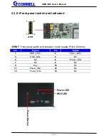
Page 18: ...ndicator JFRNT Front panel switch and indicator 14 pin header Pitch 2 54mm Pin Signal Pin Signal 1 HDD_LED 2 Power_LED 3 HDD_LED 4 NC 5 NC 6 Power_LED 7 NC 8 NC 9 Key 10 NC 11 Power_ON 12 NC 13 Power_...

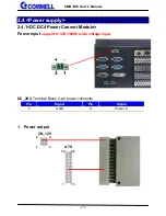
Page 19: ...Power supply 2 4 1 DC DC4 Power Convert Module Power input support 9 30V 120W wide voltage input DC_2H2 Terminal Block 2 pin power connector Pin Signal Pin Signal 1 GND 3 Power in 1 Power output 13 24...

Page 20: ...GND 3 12V 4 12V ATX main power 24 pin connector Pin Signal Pin Signal 1 3 3V 13 3 3V 2 3 3V 14 12V 3 GND 15 GND 4 5V 16 PSON 5 GND 17 GND 6 5V 18 GND 7 GND 19 GND 8 Power_OK 20 NC 9 5VSB 21 5V 10 12V...

Page 21: ...Factor PICMG1 3 Half size Backplane Extended Interface 1 x PCIe x16 slot 1 x PCIe x1 slot 1 x PCI slot CBPE 2x1P 1 x PCIe x16 slot 2 x PCI slot CBPE 1x2P Power Requirement Standard 24 pin ATX power s...

Page 22: ...r Type Main power 24 pin connector Pin Signal Pin Signal 1 3 3V 13 3 3V 2 3 3V 14 12V 3 GND 15 GND 4 5V 16 PSON 5 GND 17 GND 6 5V 18 GND 7 GND 19 GND 8 Power_OK 20 NC 9 5VSB 21 5V 10 12V 22 5V 11 12V...

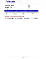
Page 23: ...l 22 Connector CN_12V Connector Type 12V 4 pin connector Pin Signal Pin Signal 1 GND 2 GND 3 12V 4 12V CN_12V for increase the input current For more information refer to the CBPE 1x2P or CBPE 2x1P Us...

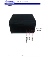
Page 24: ...CMB B72 User s Manual 23 2 6 I O Panel 2 6 1 Front Mic in USB2 0 Power LED Line out USB2 0 Power Button HDD LED...

Page 25: ...CMB B72 User s Manual 24 2 6 2 Rear DC_IN I210 AT DisplayPort COM1 COM2 COM3 COM4 VGA USB3 0 DVI D PS 2 I219 LM Expansion slots For optional cable...

Page 26: ...CMB B72 User s Manual 25 Chapter 3 Hardware Installation 3 1 Chassis Setup Procedure 3 1 1 Memory Setup Two DDR4 SO DIMM slot up to 32GB a Screw off the chassis by the indication as the picture below...

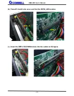
Page 27: ...CMB B72 User s Manual 26 b Take off the left side cover and find the DDR4_A B location c Insert the DDR4 SO DIMM module into the socket at 45 degree DDR4_A DDR4_B...

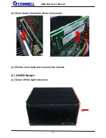
Page 28: ...CMB B72 User s Manual 27 d Press down the module with a click sound e Put the cover back and screw on the chassis 3 1 2 HDD Setup a Screw off the right side cover...

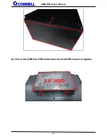
Page 29: ...CMB B72 User s Manual 28 b Put on the HDD into HDD holder then turn the HDD screws to tighten 2 5 HDD...

Page 30: ...SATA SATA power cable into HDD d Put the cover back and screw on the chassis 3 1 2 Expansion Slot Setup a Screw off the left side cover b Align the keyway of the card with the slot key and then instal...

Page 31: ...CMB B72 User s Manual 30 c Lock the bracket d Put the cover back and screw on the chassis...

Page 32: ...CMB B72 User s Manual 31 Appendix A Install Desk Wall mount a Screw on the rack mount as the picture below...

Page 33: ...our best to support you for your products projects and business Taiwan Commate computer Inc Address 19F NO 94 Sec 1 Xintai 5 th Rd Xizhi Dist New Taipei City 22102 Taiwan TEL 886 2 26963909 FAX 886 2...

Reviews: