background image


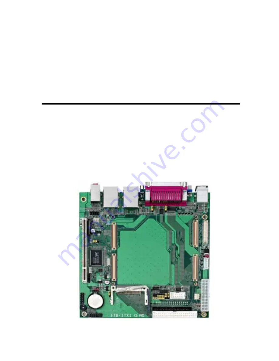
ETB-ITX1 

ETX 

Baseboard 

User’s Manual 

Edition 1.0 

2006/5/30 


Summary of Contents for ETB-ITX1

Page 1: ...ETB ITX1 ETX Baseboard User s Manual Edition 1 0 2006 5 30...

Page 2: ...ment are property of their respective owners Disclaimer The company shall not be liable for any incidental or consequential damages resulting from the performance or use of this product The company do...

Page 3: ...COM port Cable x 1 Packing List Please check the package content before you starting using the board Hardware ETB ITX1 baseboard x 1 Cable Kit ATA100 IDE Cable x1 Printed Matters User s Manual x 1 44...

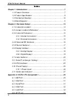
Page 4: ...1 Internal Connectors 15 2 3 2 External Connectors 15 2 4 Enhanced IDE Interface 16 2 5 Ethernet Interface 17 2 6 Display Interface 18 2 6 1 Analog Display 18 2 6 2 Digital Display 19 2 7 Audio Interf...

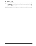
Page 5: ...ETB ITX1 User s Manual 5 Appendix B Flash BIOS 34 B 1 Flash Tool 34 B 2 Flash BIOS Procedure 34 Contact Information 35...

Page 6: ...ETB ITX1 User s Manual 6 This Page is Left for Blank...

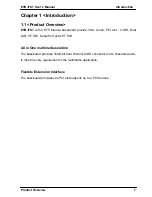
Page 7: ...rovide VGA Audio PCI slot LVDS Dual LAN CF IDE Serial Port and LPT Port All in One multimedia solution The baseboard provides 18 24 bit dual channel LVDS connector and 2 channels Audio to meet the ver...

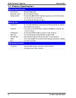
Page 8: ...connector on rear I O panel and one internal RS 232 422 485 serial port USB Port Four external Hi Speed USB 2 0 ports with 480Mbps of transfer rate on rear I O panel Parallel Port One external DB25 fe...

Page 9: ...oard audio connector with pin header built in amplifier for speaker out Expansive Interface PCI One PCI slot for supports up to 2 PCI bus master PCI devices 32 bit 33MHz Power supply 3 3V 5V Power and...

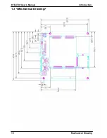
Page 10: ...ETB ITX1 User s Manual Introduction Mechanical Drawing 10 1 3 Mechanical Drawing...

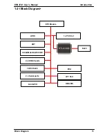
Page 11: ...ITX1 User s Manual Introduction Block Diagram 11 1 4 Block Diagram LVDS 4 x USB2 0 ports UltraDMA33 66 100 IDE 2 x Serial ports 8 bit GPIO IrDA ETX Module CRT 1 x PCI Slot LPT Port KB MS 10 100 RJ45 R...

Page 12: ...ETB ITX1 User s Manual 12 This Page is Left for Blank...

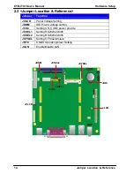
Page 13: ...l Hardware Setup Connector Location 13 Chapter 2 Hardware Setup 2 1 Connector Location ATX1 CN_INV CF JFRNT CN_DIO CN_AUDIO CN_IR PCI CN_LVDS IDE1 2 CN_WOL SYSFAN2 SYSFAN1 CN_COM1 LPT VGA COM AUDIO PS...

Page 14: ...r Function JVLCD Panel Voltage Setting JDOM IDE Pin 20 voltage setting JC3 4 Setting CN_COM1 power provide JCSEL1 Setting RS232 422 485 JCSEL2 Setting RS232 422 485 JCFSEL Setting CF Master slave JRTC...

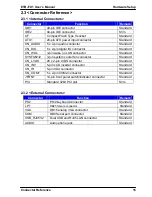
Page 15: ...ctor Standard SYSFAN1 2 3 pin system cooler fan connector Standard CN_LVDS 20 x 2 pin LVDS connector Standard CN_INV 5 pin LCD inverter connector Standard CN_IR 5 pin IrDA connector Standard CN_COM1 5...

Page 16: ...I devices with jumper JDOM for Disk on module The board also provides a Compact Flash Type II socket with jumper JCFSEL selectable Slave Master mode on secondary IDE channel Jumper JCFSEL Type onboard...

Page 17: ...tup Ethernet Interface 17 2 5 Ethernet Interface The baseboard provides two RJ45 connectors of 10 100Base T with IEEE802 3 compliance one for ETX module LAN1 The other for integrates Realtek RTL8100B...

Page 18: ...e baseboard provides one DB15 connector on real external I O port and one 40 pin LVDS interface with 5 pin LCD backlight inverter connector 2 6 1 Analog Display Please connect your CRT or LCD monitor...

Page 19: ...Interface 19 2 6 2 Digital Display The baseboard provides one 40 pin LVDS connector for 18 24 bit single dual channel panels with one LCD backlight inverter connector and one jumper for panel voltage...

Page 20: ...LCDVCC 3 GND 3 VCC3 3 3 4 GND 5 ENABKL Connector CN_LVDS Type 40 pin connector Connector model HIROSE DF13 40DP 1 25V Pin Signal Pin Signal 2 LCDVCC 1 LCDVCC 4 GND 3 GND 6 ATX0 5 BTX0 8 ATX0 7 BTX0 10...

Page 21: ...or to make a cable because every panel has its own pin assignment so we do not provide a standard cable please find a local cable manufacture to make cables LCD Installation Guide 1 Preparing the EXB...

Page 22: ...provide internal Audio connector and Phone jack on rear I O Connector CN_AUDIO Type 10 pin 2 x 5 2 54 pitch header Pin Description Pin Description 1 Line Right 2 Ground 3 Line Left 4 MIC 5 N C 6 Grou...

Page 23: ...l Port Jumper Setting The board provides two RS232 serial ports with jumper selectable 5V 12V output and RS422 485 for CN_COM1 Jumper JC3 4 Type onboard 6 pin header Pin Description Pin Description 1...

Page 24: ...ETB ITX1 User s Manual Hardware Setup Serial Port Jumper Setting 24 JCSEL1 JCSEL2 RS 232 RS 485 RS 422 1 3 10 12 1 2 5 6...

Page 25: ...a programmable 8 bit digital I O interface you can use this general purpose I O port for system control like POS or KIOSK Connector CN_DIO Type 12 pin 6 x 2 2 54mm pitch header Pin Description Pin Des...

Page 26: ...1 Power Input The baseboard requires standard ATX Power input Connector ATX1 Type 20 pin ATX power connector PIN assignment 11 3 3V 1 3 3V 12 12V 2 3 3V 13 GND 3 GND 14 PS_ON 4 5V 15 GND 5 GND 16 GND...

Page 27: ...button reset and beeper etc Please check well before you connecting the cables on the chassis Connector JFRNT Type onboard 14 pin 2 x 7 2 54 pitch header Function Signal PIN Signal Function HDLED 1 2...

Page 28: ...ETB ITX1 User s Manual IDE 28 This Page is Left for Blank...

Page 29: ...r Pin Description Pin Description 1 Reset 2 Ground 3 D7 4 D8 5 D6 6 D9 7 D5 8 D10 9 D4 10 D11 11 D3 12 D12 13 D2 14 D13 15 D1 16 D14 17 D0 18 D15 19 Ground 20 N C 21 REQ 22 Ground 23 IOW 24 Ground 25...

Page 30: ...3 D7 4 D8 5 D6 6 D9 7 D5 8 D10 9 D4 10 D11 11 D3 12 D12 13 D2 14 D13 15 D1 16 D14 17 D0 18 D15 19 Ground 20 N C 21 REQ 22 Ground 23 IOW 24 Ground 25 IOR 26 Ground 27 IORDY 28 Ground 29 DACK 30 Ground...

Page 31: ...ound 5 IRTX A 3 Serial Port Connector COM Type 9 pin D sub male connector on rear I O Pin Description Pin Description 1 DCD 6 DSR 2 SIN 7 RTS 3 SO 8 CTS 4 DTR 9 RI 5 Ground Connector CN_COM1 Type 5 x...

Page 32: ...ion Pin Description 1 RED 6 Ground 11 N C 2 GREEN 7 Ground 12 VCC 3 BLUE 8 Ground 13 HSYNC 4 N C 9 N C 14 VSYNC 5 Ground 10 Ground 15 5VCLK A 5 LAN Port Connector RJ45 Type RJ45 connector with LED on...

Page 33: ...6 Pin D Sub female Connector on rear I O Pin Description Pin Description 1 PSTB 2 PRO0 3 PRO1 4 PRO2 5 PRO3 6 PRO4 7 PRO5 8 PRO6 9 PRO7 10 ACK 11 BUSY 12 PE 13 SLCT 14 AFD 15 ERR 16 INT 17 SLIN 18 Gro...

Page 34: ...the tool is awdflash exe it s the utility that can write the data into the BIOS flash ship and update the BIOS B 2 Flash BIOS Procedure 1 Please make a bootable floppy disk 2 Get the last bin files y...

Page 35: ...to contact with us We will do our best to support you for your products projects a business Taiwan Commate Computer Inc Address 8F No 94 Sec 1 Shin Tai Wu Rd Shi Chih Taipei Hsien Taiwan TEL 886 2 26...

Reviews: