background image

FS-975M User’s Manual                                                                                          Index 


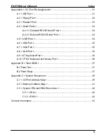
Appendix A < I/O Port Pin Assignment > .............................................................. 31 

A.1 < IDE Port > ........................................................................................... 31 

A.2 < Floppy Port > ...................................................................................... 32 

A.3 < Parallel Port > ..................................................................................... 33 

A.4 < Serial Ports> ....................................................................................... 34 

A.4.1 < Onboard RS232 Serial Ports > ............................................... 34 

A.4.2 < External RS232 Serial Port >.................................................. 34 

4.5 < USB Ports > ........................................................................................ 34 

A.6 < IrDA Port > .......................................................................................... 35 

A.7 < VGA Port >.......................................................................................... 35 

A.8 < LAN Port > .......................................................................................... 35 

A.9 < AT Keyboard Port >............................................................................. 36 

A.10 < PS/2 Keyboard and Mouse Port > .................................................... 36 

Appendix B < Flash BIOS > .................................................................................. 37 

B.1 Flash Tool............................................................................................... 37 

B.2 Flash Steps ............................................................................................ 37 

Appendix C < System Resources >...................................................................... 39 

C.1 < I/O Port Address Map > ...................................................................... 39 

C.2 < Memory Address Map > ..................................................................... 41 

C.3 < System IRQ and DMA Resources > ................................................... 42 

C.3.1 < IRQ > ...................................................................................... 42 

C.3.2 < DMA > ..................................................................................... 42 

Contact Information............................................................................................... 43 

Summary of Contents for FS-975M

Page 1: ...FS 975M Full size PICMG CPU Card User s Manual Edition 1 1 2004 08 05 1 ...

Page 2: ...in this document are property of their respective owners Disclaimer The company shall not be liable for any incidental or consequential damages resulting from the performance or use of this product The company does not issue a warranty of any kind express or implied including without limitation implied warranties of merchantability or fitness for a particular purpose The company has the right to r...

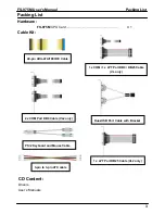
Page 3: ...d X 1 Cable Kit 40 pin UltraATA 100 IDE Cable 1 x COM 1 x LPT Port DB9 DB25 Cable VL only 2 x COM Port DB9 Cable VL2 only Dual USB Port Cable with Bracket PS 2 Keyboard and Mouse Cable 1 x LPT Port DB25 Cable VL2 only 3 pin to 3 pin ATX cable CD Content Drivers User s Manuals ...

Page 4: ...onnector location 13 2 2 Jumper Reference 14 2 3 Connector Reference 15 2 4 CPU and DRAM setting 16 2 5 CMOS Setting 18 2 6 Watchdog Timer Setting 19 2 7 Embedded Solid State Disk 20 2 8 Power and Fan Connectors 21 2 9 Display Interface 23 2 10 Ethernet Interface 24 2 11 Serial Ports 25 2 12 Switch and Indicator 26 Chapter 3 BIOS Setup 27 Chapter 4 Driver Installation 29 ...

Page 5: ...External RS232 Serial Port 34 4 5 USB Ports 34 A 6 IrDA Port 35 A 7 VGA Port 35 A 8 LAN Port 35 A 9 AT Keyboard Port 36 A 10 PS 2 Keyboard and Mouse Port 36 Appendix B Flash BIOS 37 B 1 Flash Tool 37 B 2 Flash Steps 37 Appendix C System Resources 39 C 1 I O Port Address Map 39 C 2 Memory Address Map 41 C 3 System IRQ and DMA Resources 42 C 3 1 IRQ 42 C 3 2 DMA 42 Contact Information 43 ...

Page 6: ...FS 975M Use s Manual Index 6 This page is left for blank This page is left for blank ...

Page 7: ... MHz FSB and 3GB PC133 SDRAM of system memory FS 975 offers the high end industrial computing platform with low cost Intel integrated solution The long term support onboard SSD dual Intel LAN and ISA 64mA high drive capacity also make FS 975 be the ideal solution for industrial server and workstation CTI Computer Telephony Integration VoIP Voice over IP and other high end applications Low Cost Mul...

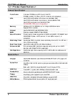
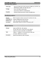
Page 8: ... Watchdog Timer Generates NMI or system reset watchdog timer with 1 to 255 sec min of time out value Real Time Clock Intel ICH2 built in RTC with lithium battery Enhanced IDE PCI enhanced IDE interface supports dual ports up to 4 ATAPI devices with UltraATA 100 supported ISA High Drive ISA 64mA high Drive capacity with TI 245 buffer on address and data bus Multi I O Port Chipset Intel 82801BA ICH2...

Page 9: ...e VGA Display Interface Chipset SiS315 Graphic Controller built in AGP 4X 256 bit 3D VGA Video Memory Onboard 32MB physical video memory Display Type CRT LCD monitor and analog display Connector External DB15 female connector on bracket for CRT Ethernet Interface Chipset Dual Intel PRO 100 LAN interface Primary LAN LAN1 Intel ICH2 and Intel 82562ET Optional secondary LAN LAN2 Intel 82559ER Type 10...

Page 10: ...X Function 3 pin ATX interface with 5V standby and power on Dimension 338 L x 122 H mm standard PICMG form factor Temperature Operating within 0 60o C 32 140 o F Storage within 20 85 o C 4 185 o F Ordering Code FS 975MVL Full size PICMG bus Socket 478 Pentium 4 Pentium 4 M CPU Card with 4xAGP SVGA 32 MB Intel PRO 100 LAN DiskOnChip Interfaces and ISA 64mA High Drive Capacity FS 975MVL2 Same as FS ...

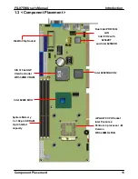
Page 11: ...ntel PRO 100 LAN Intel ICH2 with 82562ET and Intel 82559ER DiskOnChip Socket SiS 315 4xAGP VGA Controller With 32MB VRAM Intel 82801BA ICH2 Intel 82845 MCH System Memory 3 x 168 pin SDRAM Up to 3GB of capacity mPGA479 CPU Socket Intel Pentium 4 Pentium 4 processor M Celeron With 400MHz FSB ...

Page 12: ...FS 975M Use s Manual 12 This page is left for blank This page is left for blank ...

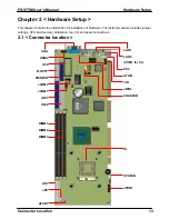
Page 13: ...nformation for installation of hardware The install procedure includes jumper settings CPU and memory installation fan I O and panel connections 2 1 Connector location VGA USBA U50 FLOPPY PRINTER JCOM2 JCOM1 IDE1 IDE2 DIMM1 DIMM2 DIMM3 ATX JPS ATXR1 LAN1 LAN2 COM1 for VL PS2 ATKB JIR JWOL CHASFAN U1 CPUFAN JFRNT ...

Page 14: ...MI Reset Setting 2 4 JDOC DiskOnChip SSD Address Setting 2 5 JDOM DiskOnModule SSD Power Setting 2 5 J82559 Secondary LAN Enable Disable Setting 2 8 JCSEL COM2 RS232 422 485 Mode Setting 2 10 J1 COM2 RS232 422 485 Mode Setting 2 10 J2 COM2 RS232 422 485 Mode Setting 2 10 JP4M Pentium 4 Pentium 4 M processor setting JCSEL J82559 J2 JDOC JWDT JP4M J1 JRTC JDOM ...

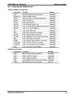
Page 15: ... Port Standard JIR 10 pin SIR IrDA Port Standard U50 32 pin DIP DiskOnChip Socket Standard JATKB 5 pin AT Keyboard Connector Standard ATXR1 4 pin Additional 12V Power Connector Standard JPS 3 pin ATX Signal Connector Standard JFRNT 14 pin Switch and Indicator Connector Standard CPUFAN 3 pin 12V CPU Fan Connector Standard SYSFAN 3 pin 12V System Fan Connector Standard WOL 3 pin Wake On LAN Interfac...

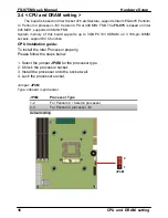
Page 16: ...ory of this board supports up to 3GB PC133 SDRAM on 3 168 pin DIMM sockets support ECC function CPU installation guide To install the Intel Processor properly Please follow the steps below 1 Select the jumper JP4M for the processor type 2 Unlock the processor socket 3 Install the processor onto the socket well 4 Lock the processor socket Jumper JP4M Type onboard 3 pin header JP4M Processor Type 1 ...

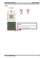
Page 17: ...e Setup CPU and DRAM Setting 17 Unless you set the jumper and lock the processor well the board will not work properly Lock switch Unlock Lock Notice Before you install the processor on the socket please check the pin director well ...

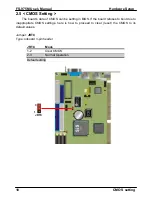
Page 18: ... s data of CMOS can be setting in BIOS If the board refuses to boot due to inappropriate CMOS settings here is how to proceed to clear reset the CMOS to its default values Jumper JRTC Type onboard 3 pin header JRTC Mode 1 2 Clear CMOS 2 3 Normal Operation Default setting 3 JRTC 1 ...

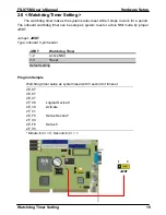
Page 19: ...g timer can be setup as system reset or active NMI mode by jumper JWDT Jumper JWDT Type onboard 3 pin header JWDT Watchdog Timer 1 2 Active NMI 2 3 Reset Default setting Program Sample Watchdog timer setup as system reset with 5 second of timeout 2E 87 2E 87 2E 07 2F 08 Logical Device 8 2E 30 Activate 2F 01 2E F5 Set as Second 2F 00 2E F6 Set as 5 2F 05 Minute bit 3 0 Second bit 3 1 3 1 JWDT ...

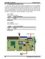
Page 20: ...ash disk in 32 pin DIP JEDEC with jumper selectable address on jumper JDOC onboard 40 pin IDE2 box header supports normal DOM DiskOnModule or M systems DiskOnChip IDE Pro flash disk with jumper selectable 5V VCC power for cable free applications on jumper JDOM Jumper JDOC Type onboard 3 pin header JDOC DiskOnChip Address 1 2 D000h 2 3 D800h Default setting Jumper JDOM Type onboard 2 pin header JDO...

Page 21: ...rs The board provides one standard 20 pin ATX power connector and one 4 pin P4 use 12V power connector and one 3 pin ATX power on connector You can use this board with a backplane or simply connect it with a standard ATX power supply CHASFAN 3 1 ATX 10 20 1 11 CPUFAN 3 1 1 2 ATXR1 3 1 JPS 3 4 ...

Page 22: ...tion Pin Description Pin Description 1 5V Standby 2 Ground 3 Power On Connector CPUFAN SYSFAN Type 3 pin Fan Power Wafer Connector Pin Description Pin Description Pin Description 1 Ground 2 12V 3 Fan Control Connector ATX Type 20 pin Standard ATX Power Connector Pin Description Pin Description 1 N C 11 Vcc 2 N C 12 Vcc 3 Ground 13 5V 4 Vcc 14 Ground 5 Ground 15 Ground 6 Vcc 16 Ground 7 Ground 17 P...

Page 23: ...lay Interface 23 2 9 Display Interface The board is integrated with SiS315 Graphic Controller with 256 128 bit 3D 2D engine and 32MB physical video memory The CRT analog VGA interface includes one external DB15 female connector on bracket VGA ...

Page 24: ...le or disable by jumper J82559 The primary LAN interface is controlled by Intel ICH2 with Intel 82562ET PHY and setting as LAN1 It provides the same performance as Intel 82559 LAN with the same driver The secondary LAN interface is controlled by Intel 82559ER chipset and setting as LAN2 Jumper J82559 Type onboard 3 pin header J82559 LAN2 Enable Disable Setting 1 2 Enable 2 3 Disable Default settin...

Page 25: ...jumper selectable RS232 422 485 COM2 The configuration of COM2 can be setting with jumper J1 J2 and JCSEL Jumper J1 J2 JCSEL Type onboard 4 6 12 pin header COM2 Mode J1 J2 JCSEL RS 232C OFF 5 6 1 2 4 5 7 8 10 11 RS 422 3 4 3 4 2 3 5 6 8 9 11 12 RS 485 1 2 1 2 2 3 5 6 8 9 11 12 Default setting 1 4 10 7 2 4 2 6 6 9 JCSEL 12 3 1 3 J1 5 1 J2 ...

Page 26: ...witch and Indicator 2 14 1 13 Connector JFRNT Type onboard 14 pin 2 x 7 2 54 pitch header Function Signal PIN Signal Function Vcc 1 2 Vcc IDE LED Active 3 4 N C Reset 5 6 GND Power LED Reset GND 7 8 Vcc N C 9 10 N C PWRBT 11 12 N C Power Button GND 13 14 SPKIN Speaker ...

Page 27: ...ains the information when the power is turned off If the battery runs out of the power then the settings of BIOS will come back to the default setting The BIOS section of the manual is subject to change without notice and is provided here for reference purpose only The settings and configurations of the BIOS are current at the time of print and therefore they may not be exactly the same as that di...

Page 28: ...FS 975M Use s Manual 28 This page is left for blank This page is left for blank ...

Page 29: ... LAN driver 82562ET This item will install the Intel 82562ET Ethernet controller driver Install LAN driver 82559ER This item will install the Intel 82559ER Ethernet controller driver Install Microsoft DirectX This Item will update the last Microsoft DirectX utility Link to website to download the updated drivers This item will re direct you to our support page on website to download the last drive...

Page 30: ...FS 975M Use s Manual 30 This page is left for blank This page is left for blank ...

Page 31: ...8 D10 9 D4 10 D11 11 D3 12 D12 13 D2 14 D13 15 D1 16 D14 17 D0 18 D15 19 Ground 20 N C VCC 21 REQ 22 Ground 23 IOW STOP 24 Ground 25 IOR HDMARDY 26 Ground 27 IORDY DDMARDY 28 IDESEL 29 DACK 30 Ground 31 IRQ 32 N C 33 A1 34 CBLID 35 A0 36 A2 37 CS0 MASTER CS 38 CS1 SLAVE CS 39 LED ACT 40 Ground Note The pin 20 of IDE2 is jumper selectable as 5V VCC for the DOM DiskOnModule or DiskOnChip IDE Pro fla...

Page 32: ... 0 3 Ground 4 DRIVE DENSITY SELECT 1 5 Ground 6 N C 7 Ground 8 INDEX 9 Ground 10 MOTOR ENABLE A 11 Ground 12 DRIVER SELECT B 13 Ground 14 DRIVER SELECT A 15 Ground 16 MOTOR ENABLE B 17 Ground 18 DIRECTION 19 Ground 20 STEP 21 Ground 22 WRITE DATA 23 Ground 24 WRITE GATE 25 Ground 26 TRACK 0 27 Ground 28 WRITE PROTECT 29 Ground 30 READ DATA 31 Ground 32 HEAD SELECT 33 Ground 34 DISK CHANGE ...

Page 33: ...er Type 26 pin box header 25 1 Pin Description Pin Description 1 STROBE 14 AUTO FEED 2 D0 15 ERROR 3 D1 16 INITIALIZE 4 D2 17 SELECT INPUT 5 D3 18 Ground 6 D4 19 Ground 7 D5 20 Ground 8 D6 21 Ground 9 D7 22 Ground 10 ACKNOWLEDGE 23 Ground 11 BUSY 24 Ground 12 PAPER EMPTY 25 Ground 13 SELECT 26 N C ...

Page 34: ...7 RTS 8 CTS 9 RI 10 N C A 4 2 External RS232 Serial Port 5 4 3 2 1 9 8 7 6 Connector COM1 FS 975MVL only Type 9 pin D sub male connector on bracket Pin Description Pin Description 1 DCD 2 RXD 3 TXD 4 DTR 5 Ground 6 DSR 7 RTS 8 CTS 9 RI 4 5 USB Ports 6 10 Connector USBA Type 10 pin 2 x 5 header for dual USB Ports 1 5 Pin Description Pin Description 1 VCC 6 VCC 2 Data0 7 Data1 3 Data0 8 Data1 4 Grou...

Page 35: ... IRTX 10 N C 6 10 A 7 VGA Port 1 2 3 4 5 11 12 13 14 15 Connector VGA Type 15 pin D sub female connector on bracket Pin Description Pin Description Pin Description 1 RED 6 Ground 11 N C 2 GREEN 7 Ground 12 VDDAT 3 BLUE 8 Ground 13 HSYNC 4 N C 9 VCC 14 VSYNC 5 Ground 10 Ground 15 VDCLK A 8 LAN Port 1 8 Connector LAN1 LAN2 FS 975VL2 only Type RJ45 connector on bracket Pin 1 2 3 4 5 6 7 8 Description...

Page 36: ...CLK DATA N C Ground VCC A 10 PS 2 Keyboard and Mouse Port 3 4 1 2 5 6 Connector PS2 Type 6 pin MiniDIN connector on bracket Pin 1 2 3 4 5 6 Description KBD MSD Ground N C KBC MSC Note The PS 2 connector supports standard PS 2 keyboard directly or both PS 2 keyboard and mouse through the PS 2 Y type cable The cable is the standard on packing list ...

Page 37: ...o flash tool You can download the tool online at the address below http www award com File name of the tool is awdflash exe it s the utility that can write the data into the BIOS flash ship and update the BIOS B 2 Flash Steps 1 Get the bin file including the image of new BIOS you want to update 2 Power on the system and flash the BIOS 3 Re start the system ...

Page 38: ...FS 975M Use s Manual 38 This page is left for blank This page is left for blank ...

Page 39: ...oard Resource x0094 x009F Direct Access Memory Controller x00A0 x00A1 Programmable Interrupt Controller x00A2 x00BF Motherboard Resource x00C0 x00DF Direct Access Memory Controller x00E0 x00EF Motherboard Resource x00F0 x00FF Numeric Data Processor x0170 x0177 Intel R 82801BA Ultra ATA Storage Controller 244B x0170 x0177 Secondary IDE controller dual fifo x01F0 x01F7 Intel R 82801BA Ultra ATA Stor...

Page 40: ...otherboard Resource x0F78 x0F7B Motherboard Resource x0FBC x0FBF Motherboard Resource x9000 x907F SiS315 x9000 x9FFF Intel R 845 Chipset Processor to AGP Controller 1A31 xA000 xA03F Intel R PRO 100 VE Desktop Adapter xA000 xAFFF Intel R 82801BA PCI Bridge 244E xA400 xA43F Intel R GD82559ER PCI Adapter xB000 xB01F Intel R 82801BA BAM USB Universal Host Controller 2442 xB800 xB81F Intel R 82801BA BA...

Page 41: ...ACPI BIOS x1FFF0000 x1FFFFFFF System board extension for ACPI BIOS xD0000000 xDFFFFFFF Intel R 845 Chipset Processor to AGP Controller 1A31 xD0000000 xDFFFFFFF SiS315 xE0000000 xE3FFFFFF Intel R 845 Chipset Processor to I O Controller 1A30 xE4000000 xE400FFFF SiS315 xE4000000 xE5FFFFFF Intel R 845 Chipset Processor to AGP Controller 1A31 xE5000000 xE503FFFF SiS315 xE6000000 xE7FFFFFF Intel R 82801...

Page 42: ...M USB Universal Host Controller 2442 9 ACPI IRQ Holder for PCI IRQ Steering 9 SCI IRQ used by ACPI bus 10 Intel R 82801BA BAM SMBus Controller 2443 10 Intel R GD82559ER PCI Adapter 10 ACPI IRQ Holder for PCI IRQ Steering 11 Intel R PRO 100 VE Desktop Adapter 11 ACPI IRQ Holder for PCI IRQ Steering 12 PS 2 Compatible Port 13 Numeric Data Processor 14 Primary IDE controller dual fifo 14 Intel R 8280...

Page 43: ...ll do our best to support you for your products projects and business COMMELL Industrial Computer Taiwan Commate Computer Inc COMMELL www commell com tw Your Embedded Applied Computer Partner Address 8F No 94 Sec 1 Shin Tai Wu Rd Shi Chih Taipei Hsien Taiwan TEL 886 2 26963909 FAX 886 2 26963911 Website http www commell com tw E mail info commell com tw General Information tech commell com tw Tech...

Reviews: