background image


HE-860 User’s Manual 

Table of Contents 

Chapter 1.    Introduction ...................................................................... 3


1.1


Product Overview ........................................................................ 3


1.2


Specification ................................................................................ 4


1.3


Component Placement ................................................................ 7


1.4


Block Diagram ............................................................................. 8


Chapter 2.  Hardware Setup ................................................................ 9


2.1


Jumpers and Connectors Location.............................................. 9


2.2


CPU Setting............................................................................... 12


2.3


CMOS Setting ........................................................................... 12


2.4


Watchdog Timer Setting ............................................................ 13


2.5


Embedded Flash Disk ............................................................... 14


2.6


Power and Fan Connectors....................................................... 15


2.7


Display Interface........................................................................ 16


2.8


Ethernet Interface...................................................................... 17


2.9


Audio Interface .......................................................................... 18


2.10


Serial Port COM2 Mode Configuration ...................................... 19


2.11


Switches and Indicators ............................................................ 20


Chapter 3.  BIOS Setup...................................................................... 21


Chapter 4.  Driver Installation ........................................................... 23


4.1


Install Board’s Software ............................................................. 23


4.2


Install Ultra ATA IDE Driver ........................................................ 23


4.3


Install VGA Driver ...................................................................... 23


4.4


Install LAN Driver ...................................................................... 23


4.5


Install Audio Driver .................................................................... 23


4.6


Link to <

 Website 

> Homepage ................................................. 23


4.7


Browse this CD.......................................................................... 23


Summary of Contents for HE-860

Page 1: ...Setting 13 2 5 Embedded Flash Disk 14 2 6 Power and Fan Connectors 15 2 7 Display Interface 16 2 8 Ethernet Interface 17 2 9 Audio Interface 18 2 10 Serial Port COM2 Mode Configuration 19 2 11 Switche...

Page 2: ...source 28 Appendix B Flash the BIOS 29 B 1 BIOS Auto Flash Tool 29 B 2 Flash Method 29 Appendix C I O Port Pin Assignment 31 C 1 IDE Port 31 C 2 Floppy Port 32 C 3 Parallel Port 33 C 4 RS 232 Serial P...

Page 3: ...n platform with 533 MHz of speed at 133 MHz of FSB provides 1 GBytes sec of data transfer rate Based on x86 architecture and VIA s latest technology HE 860 supports most of the x86 based OS and AP Tha...

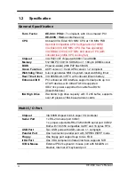
Page 4: ...86B built in RTC with onboard lithium battery Enhanced IDE PCI enhanced IDE interface supports dual ports up to 4 ATAPI devices with UltraATA 100 supported IDE2 Vcc power supported for cable free DOM...

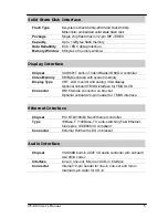
Page 5: ...ory Display Type CRT LCD monitor and analog VGA display Optional onboard TMDS interface for TMDS LCD Connector DB15 female connector on bracket Optional onboard 20 pin header for TMDS interface Ethern...

Page 6: ...ISA High Drive Capacity HE 860VXL Same as HE 860VL but with onboard TMDS Panel Link Interface HE 860SVL Half size ISA bus Embedded VIA Eden CPU Card with onboard VIA Eden 533MHz CPU VGA LAN Audio Dis...

Page 7: ...A686B Chipset VIA 8601T Chipset Phoenix Award BIOS TMDS Interface DiskOnChip Socket Embedded VIA Eden C3 CPU VIA Eden Ultra Low Voltage CPU for Fan Free Operation VIA EBGA C3 CPU with Onboard CPU Cool...

Page 8: ...SB 100 133 MHz PC133 ATAPI Device PISA Backplane PCI Bus Interface PS 2 Keyboard PS 2 Mouse Floppy Serial Device Parallel Device USB Devices Codec Audio Devices DiskOnChip CRT LCD Monitor 10 100 Mbps...

Page 9: ...er settings CPU and memory installation fan I O and panel connections 2 1 Jumpers and Connectors Location VGA LAN_CON1 COM1 PS2 JAT_KB JLAN JRTC SIR JPVOD1 VXL Only JTMDS SWDT JDOC JWDT DOC U5 CPUFAN...

Page 10: ...Timer Setting 2 4 SWDT Watchdog Timer Timeout Value Setting 2 4 JDOC DiskOnChip Address Setting 2 5 1 JDOM DiskOnModule Power Setting 2 5 2 JPVOD1 TMDS Voltage Setting 2 7 JLAN LAN Enable Disable Set...

Page 11: ..._KB 5 pin AT PC Keyboard Connector Standard SIR 5 pin SIR Infrared Port Standard PWRCON1 6 pin AT P8 Power Connector Standard ATXCON 3 pin ATX Signal Connector Standard JFRNT 10 pin Front Panel Connec...

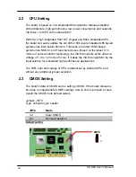
Page 12: ...soe Based on the latest 0 13 micron of semi conductor technology the VIA Eden works at the ultra low voltage of 1 0 to 1 2 Volts of Vcore It makes the VIA Eden platform be the ideal solution for embed...

Page 13: ...3 pin header JWDT Watchdog Timer 1 2 Active NMI 2 3 Reset Default setting 2 4 2 Watchdog Timer Time out Value Setting Jumper SWDT Type onboard 4 way DIP Switch Time out Value SWDT 1 Sec OFF OFF ON OFF...

Page 14: ...rd 40 pin IDE2 box header supports normal DOM DiskOnModule or M systems DiskOnChip IDE Pro flash disk with jumper selectable 5V Vcc power for cable free applications on jumper JDOM 2 5 1 DiskOnChip 20...

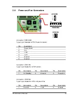
Page 15: ...d 2 Vcc 3 12V 4 12V 5 Ground 6 Ground Connector ATXCON Type 3 pin Header for ATX Function Pin Description Pin Description Pin Description 1 5V Standby 2 Ground 3 Power On Connector CPUFAN Type 3 pin H...

Page 16: ...bracket an optional TMDS panel link interface via onboard 20 pin header JTMDS and voltage jumper JPVOD1 Jumper JPVOD1 Type onboard 3 pin header JPVOD1 TMDS Panel Voltage Setting 1 2 5V 2 3 3 3V Defaul...

Page 17: ...the 10Base T 100Base TX auto switching Fast Ethernet interface with full duplex and IEEE 802 3U compliant connects with RJ45 connector on bracket The LAN function can enable or disable by jumper JLAN...

Page 18: ...dec provides line in line out Mic in and CD in interfaces Connector JAUDIO Type 10 pin header Pin Description Pin Description 1 Line Right 2 Ground 3 Line Left 4 MIC 5 MIC 6 Ground 7 N C 8 Line Out Le...

Page 19: ...JCSEL1 JCSEL JCSEL2 J2 Type onboard 6 12 pin header COM2 Mode JCSEL2 J2 JCSEL1 JCSEL RS 232 1 2 1 2 4 5 7 8 10 11 RS 422 5 6 2 3 5 6 8 9 11 12 RS 485 3 4 2 3 5 6 8 9 11 12 Default setting Connector JC...

Page 20: ...ound Reset 7 PWR BN 8 Ground Power Button 9 Speaker 10 Vcc Speaker 10 pin JFRNT includes additional speaker and power LED cables in the packing list Connector JFRNT Type II Type onboard 14 pin header...

Page 21: ...out notice and is provided here for reference purpose only The settings and configurations of the BIOS are current at the time of print and therefore they may not be exactly the same as that displayed...

Page 22: ...HE 860 User s Manual 22 Notes This page left blank intentionally...

Page 23: ...selection helps you to install the driver of IDE interface 4 3 Install VGA Driver The selection helps you to install the driver of onboard VGA interface 4 4 Install LAN Driver The selection helps you...

Page 24: ...HE 860 User s Manual 24 Notes This page left blank intentionally...

Page 25: ...x0274 0x0277 ISAPNP Read Data Port 0xD000 0xD00F VIA Bus Master IDE Controller 0x01F0 0x01F7 Primary IDE Channel 0x03F6 0x03F6 Primary IDE Channel 0x0170 0x0177 Secondary IDE Channel 0x0376 0x0376 Sec...

Page 26: ...ey 0x0064 0x0064 PC AT Enhanced PS 2 Keyboard 101 102 Key 0x0378 0x037F Printer Port LPT1 0x03F8 0x03FF Communications Port COM1 0x02F8 0x02FF Communications Port COM2 0x03F0 0x03F5 Standard floppy di...

Page 27: ...FFFFF VIA Tech VT8361 VT8601 Graphics Controller 5 12 01 3105 0xE6000000 0xE601FFFF VIA Tech VT8361 VT8601 Graphics Controller 5 12 01 3105 0xE5000000 0xE57FFFFF VIA Tech VT8361 VT8601 Graphics Contro...

Page 28: ...8 System CMOS real time clock 9 free 10 VIA Tech VT8361 VT8601 Graphics Controller 4 12 01 3105 11 Realtek RTL8139 A B C 8130 PCI Fast Ethernet NIC 11 VIA Tech 3038 PCI to USB Universal Host Controlle...

Page 29: ...ell com tw Support Support htm File name of the tool is awdflash exe it s the utility that can write the data into the BIOS flash ship and update the BIOS B 2 Flash Method 1 Get the bin file including...

Page 30: ...HE 860 User s Manual 30 Notes This page left blank intentionally...

Page 31: ...D2 14 D13 15 D1 16 D14 17 D0 18 D15 19 Ground 20 N C Vcc 21 REQ 22 Ground 23 IOW STOP 24 Ground 25 IOR HDMARDY 26 Ground 27 IORDY DDMARDY 28 IDESEL 29 DACK 30 Ground 31 IRQ 32 N C 33 A1 34 CBLID 35 A0...

Page 32: ...T 1 5 Ground 6 N C 7 Ground 8 INDEX 9 Ground 10 MOTOR ENABLE A 11 Ground 12 DRIVER SELECT B 13 Ground 14 DRIVER SELECT A 15 Ground 16 MOTOR ENABLE B 17 Ground 18 DIRECTION 19 Ground 20 STEP 21 Ground...

Page 33: ...Pin Description Pin Description 1 STROBE 14 AUTO FEED 2 D0 15 ERROR 3 D1 16 INITIALIZE 4 D2 17 SELECT INPUT 5 D3 18 Ground 6 D4 19 Ground 7 D5 20 Ground 8 D6 21 Ground 9 D7 22 Ground 10 ACKNOWLEDGE 23...

Page 34: ...eader Pin Description Pin Description 1 DCD 2 RXD 3 TXD 4 DTR 5 Ground 6 DSR 7 RTS 8 CTS 9 RI 10 N C C 4 2 On Bracket RS 232 Serial Port Connector COM1 Type 9 pin D sub male connector on bracket Pin D...

Page 35: ...header for dual USB Ports Pin Description Pin Description 1 Vcc 6 Vcc 2 Data0 7 Data1 3 Data0 8 Data2 4 Ground 9 Ground 5 Ground 10 Ground C 6 IrDA Port Connector SIR Type 5 pin header for SIR Ports P...

Page 36: ...Pin Description Pin Description 1 RED 6 Ground 11 N C 2 GREEN 7 Ground 12 VDDAT 3 BLUE 8 Ground 13 HSYNC 4 N C 9 Vcc 14 VSYNC 5 Ground 10 Ground 15 VDCLK C 8 LAN Port Connector LAN_CON1 Type RJ45 con...

Page 37: ...10 PS 2 Keyboard and Mouse Port Connector PS2 Type 6 pin MiniDIN connector on bracket Pin 1 2 3 4 5 6 Description KBD MSD Ground N C KBC MSC Note The PS 2 connector supports standard PS 2 keyboard di...

Reviews: