LP-172 User’s Manual
-
21
-
Connector:
CN_INV
Type: 5-pin Inverter power connector
Connector model:
molex_53261-5pin
Pin
Description
1 +3.3V
2 CTLBKL
3 +5V
4 GND
5 Enable
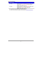
Jumper:
JVLCD
Type: 3-pin Power select jumper
Pin
Description
1-2
+5V
2-3
+3.3V
Default: 2-3
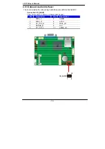
Connector:
CN_LVDS
Type: onboard 20-pin connector for LVDS connector
Connector model:
HIROSE DF13-20DP-1.25V
Pin
Signal
Pin
Signal
1 LCDVCC 2 LCDVCC
3 NC
4 GND
5 TX0N
6 TX0P
7 GND
8 TX1N
9 TX1P
10 GND
11 TX2N
12 TX2P
13 GND
14 TXCN
15 TXCP
16 GND
17 RDVI_DA 18 RDVI_SL
19 NC
20 NC
To setup the LCD, you need the component below:
1.
A panel with LVDS interfaces.
2.
An inverter for panel’s backlight power.
3.
A LCD cable and an inverter cable.
For the cables, please follow the pin assignment of the connector to make a cable, because
every panel has its own pin assignment, so we do not provide a standard cable; please find
a local cable manufacture to make cables.
Summary of Contents for LP-172
Page 1: ...LP 172 Pico ITX User s Manual 2012 03 27 Version 1 0...
Page 6: ...LP 172 User s Manual 5 This page is left for blank...
Page 10: ...LP 172 User s Manual 9 1 3 Mechanical Drawing...
Page 13: ...LP 172 User s Manual 12 RJ45 PS2 CRT CN_INV DC_OUT SO DIMM LP 172...
Page 32: ...LP 172 User s Manual 31 This Page is Left For Blank...
Page 34: ...LP 172 User s Manual 33 This Page is Left for Blank...
Page 38: ...LP 172 User s Manual 37 Appendix C System Resources C 1 I O Port Address Map...
Page 39: ...LP 172 User s Manual 38...
Page 40: ...LP 172 User s Manual 39 C 2 Memory Address Map...
Page 41: ...LP 172 User s Manual 40 C 3 System IRQ Resources...
Page 42: ...LP 172 User s Manual 41...
Page 43: ...LP 172 User s Manual 42...


