LV-67A User’s Manual
21
2.9 <Onboard Display Interface>
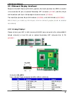
Based on Intel Q45 chipset with built-in graphics, the board provides one DB15 Connector
on real external I/O port, or optional Secondary CRT connector
(LV-67AT)
and One 40-pin
LVDS interface with 5-pin LCD backlight inverter connector.
(LV-67AX)
The board also provides 26-pin DVI interface
(LV-67AD)
or two DVI interface
(LV-67AD2)
Notice: When you install any PCI Graphic card, the onboard graphics would be disabled
automatically.
2.9.1 <Analog Display>
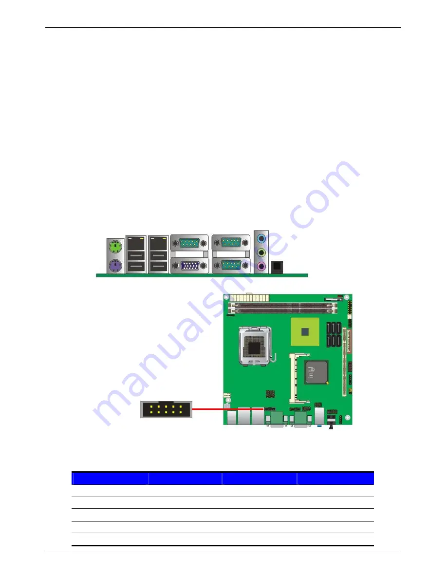
Please connect your CRT or LCD monitor with DB15 male connector to the onboard DB15
female connector on rear I/O port or optional Secondary CRT connector Dip 10 Pin
(LV-67AT)
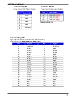
Connector:
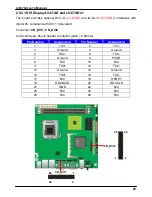
CN_CRT2
Type: onboard 10-pin connector for CRT2 (Pitch = 2.00 mm)
Pin
Signal
Pin
Signal
2
CRT2 DDC_DA
1
CRT2 DDC_DC
4 CRT2
R
3 GND
6
CRT2 G
5
CRT2 B
8
CRT2 HSYNC
7
CRT2 VSYNC
10 GND
9 GND
CRT1
CN_CRT2
1
2
9
10
Summary of Contents for LV-67A
Page 1: ...LV 67A Mini ITX motherboard User s Manual Edition 1 2 2009 06 11 ...
Page 6: ...LV 67A User s Manual 6 This Page is Left for Blank ...
Page 11: ...LV 67A User s Manual 11 1 4 Mechanical Drawing Unit inch ...
Page 37: ...LV 67A User s Manual 37 This Page is Left for Blank ...
Page 49: ...LV 67A User s Manual 49 This Page is Left for Blank ...
Page 53: ...LV 67A User s Manual 53 Appedix B System Resources B 1 I O Port Address Map ...
Page 54: ...LV 67A User s Manual 54 ...
Page 55: ...LV 67A User s Manual 55 B 2 Memory Address Map ...
Page 56: ...LV 67A User s Manual 56 B 3 System IRQ Resources ...


