15
14
Operation (continued)
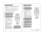
Measuring diode
Operation (continued)
3
CAUTION: To avoid the meter or measured
equipment from being damaged, cut off all
power supply of measured circuits and
discharge all high voltage capacitors
before measuring diode.
□
Turn the rotary switch to the
position (1).
□
Press the FUNC key (2) and select the
measuring range.
□
Separately connect the black and read
test leads to the negative pole and
positive pole of the measured diode.
□
The meter displays the forward bias value
of the measured diode. If the poles of the
test leads are connected inversely, the
meter will display “OL”.
For on-line measuring diode, the
meter displays the forward voltage
drop at forward measurement; the
reverse
measurement depends on
the values of other elements
connected in parallel at both ends
of diode.
Measuring continuity
4
CAUTION: To avoid the meter or measured
equipment from being damaged, cut off all
power supply of measured circuits and
discharge all high voltage capacitors before
continuity measurement.
□
Turn the rotary switch to the
position (1).
□
Press the FUNC key (2) and select the
measuring range.
□
Separately connect the two ends of the
test leads to the end ends of the
measured
part and circuit.
□
The meter displays the approximate
resistance value between measured
points. Here if the resistance value
between measured points is less than
50±20 Ω, the buzzer will make a sound.


