10
If an external signal from an external device has to be processed by the robot control system,
this can be given to one of the digital inputs (DInX).
The digital inputs are always galvanically isolated from the robot control system by means of
an optocoupler with 12K current limiting resistor, so as to connect both signal and 0V to the
external device. The positive signal is fed to DIn1-4 of the 5-pin plug-in connector, flows via the
12K resistor through the optocoupler diode to the GND of the 5-pin connector.
*See 10.1 Galvanic isolation
4.2.2
Internal digital I/Os
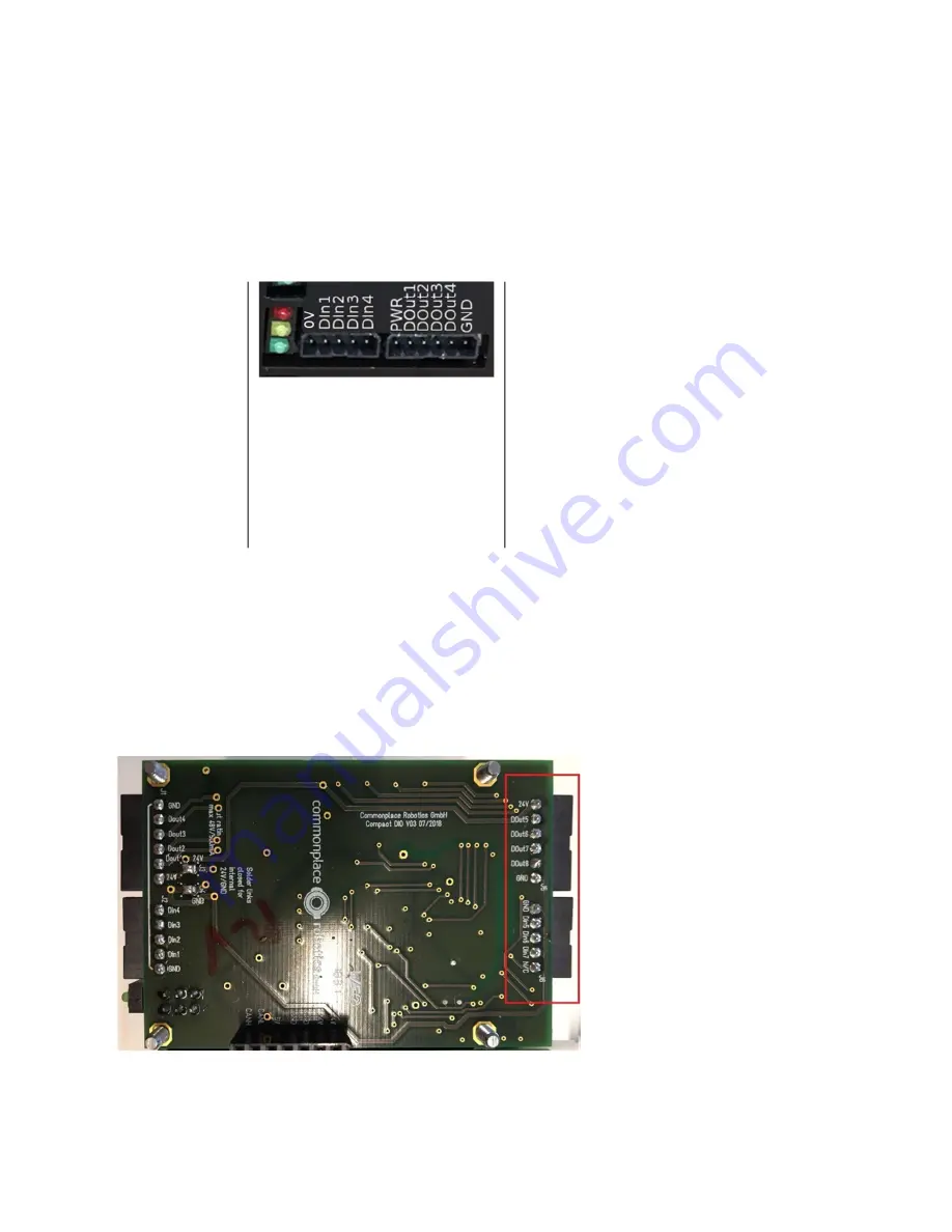
If further inputs and outputs are required, 3 additional ones are available internally in the
housing of the robot on the rear side of the DIO module. To reach them, the robot must be
placed on its side. Here DOut 5,6,7 (DOut8 is not occupied) and DIn 5,6,7 are available.
Diagram 4: Additional internal digital I/Os.
Digital I/O
module
0V: External Ground (-)
DIn<X>: Digital input (+)
GND: 0V of the robot control
system*
PWR: 24V of the robot control
system**
DOut<X>: Digital output (24V of the
robot controller) e.g. for controlling a
gripper.


