24
10.
Extensions / Adjustments
10.1
Galvanic isolation of digital outputs
If an external device with a different potential than the robot control system (for example a
self-powered LED) has to be switched, the DOut pins must be disconnected from the robot's
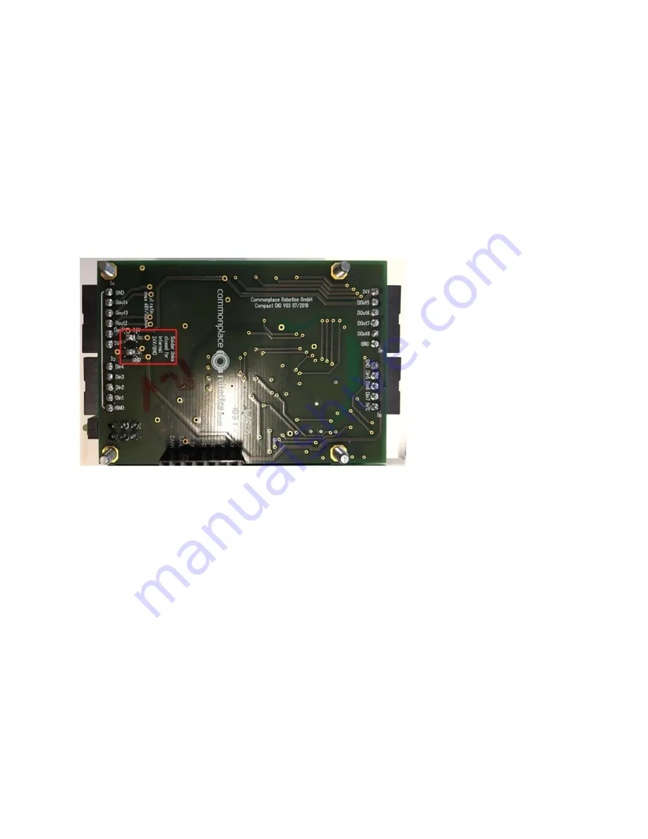
24V supply voltage GND. This can be achieved by disconnecting solder links J3 and J4 of the
DIO board. J3 and J4 are accessible from below the robot. They are marked red in the picture
below.
Diagram 7: Galvanic isolation of the digital outputs


