background image


29 


Program does not start, error 
message e.g. „The Application 
could not be initialized 
correctly (0xc0000135). “  

Is the Microsoft .NET-
Framework missing?  

Install the current .NET framework 
from the Microsoft homepage 

Program does not start, error 
message: "CPRog has 
encountered a problem and 
needs to close”. 

Is and DirectX file missing? 
These files are necessary for 
joypad and audio 
functionalities. 

Install DirectX Version 9.0c for 
your system. Links can be found 
using any search engine. 

Program does not start, error 
message: „CPRog does not 
work any more” 

If running on Windows 7: If 
CPRog is installed at 
c:\Programs or c:\Programs 
(x86) it can be started only 
with administrator rights.  

Right-click on the CPRog link on the 
desktop, choose „start as 
administrator” 

9.2


Software CPRog 

Error 

Possible Cause 

Measures 

Connection loss 

The robot expects periodically 
a message from the CPRog 
computer. If this does not have 
sufficient free computing 
power, the break between two 
messages may be too long. 

Reset the errors and free the 
motors, restart the program, see 
section 5.3. 
Avoid these problems by closing 
further programs, eventually 
disabling the network connection 
and the virus scanner. 

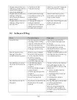
Does not move any more: 
Message “Virtual Box 
violated” and warning sound. 

When moving in „Cartesian 
Mode” the robot cannot get 
out of a virtual box. In “Joint 
Mode“ this is possible, 
changing back in CartMode 
may lead to these warnings. 

Change to JointMode and move the 
robot back into the virtual Box, e.g. 
into a standard position. 

The robot does not connect, 
the connect button does not 
work.  
 

Is the USB-CAN adapter 
plugged in, are the driver 
installed? 
Is the mains adapter plugged 
and switched on? 
Is the EmergencyStop button 
released? 
Do the green status LEDs in 
the joint modules blink? 

You can find further information in 
the Log-Messages window. The 
LED of the USB interface provides 
information: 


LED on: connected with the 
Windows driver 


LED blinks slowly: connected 
with CPRog 


LEDblinks fast: data are 
transferred


The robot does not react to 
the joypad  
 

Has it been activated? Was the 
Mode button on the joypad 
pressed? 
 

The Log-Messages windows shows 
you if the joypad has been 
connected correctly. 
When the red light beneath the 
mode button of the joypad is on, 
you have to press the mode button 
once again. 

Summary of Contents for Robot arm mower 4

Page 1: ...1 Bedienungsanleitung Mover4...

Page 2: ...2...

Page 3: ...429 374983 4 info cpr robots com www cpr robots com The CE sign confirms that this product meets the requirements of the directive 2004 108 EC EMC and 2002 95 EC RohS The according documentation is de...

Page 4: ...lation of the Driver for the USB Adapter 12 3 5 Licensing 13 4 Robor Arm Mover4 14 4 1 Geometry 14 4 2 Digital Inputs and Outputs 15 4 3 Mounting Flange for the Gripper 15 4 4 Drawing of the Robot Bas...

Page 5: ...dit 24 7 Configuration 25 7 1 Application Configuration CPRFrontend xml 25 7 2 Robot Configuration Software 26 7 3 Robot Configuration Hardware 26 8 Interfacing 27 8 1 Command External Motion 27 8 2 C...

Page 6: ...e used by children without the supervision by adults Not suited for children below 3 years Small parts pose choking hazards Sharp or otherwise dangerous tools or parts must not be mounted on the robot...

Page 7: ...odules with aluminum profiles Each joint module contains a servo motor The front end of the robot the flange allows mounting a gripper or another tool The robot base has to be fastened on a stand or a...

Page 8: ...e flange 2 digital Outputs 5V 2 digitale Ausg nge 5V 25 mA und 12V 0 5A supply via Harting SEK 6 poles Communication Definition of position setpoints for all four joints with 50 Hz cycle Reading of th...

Page 9: ...g the Power Supply and the USB Adapter Pic 2 Cable loom and USB adapter The cable loom connects the power supply the USB adapter and the robot as depicted above All connectors fit only one way Before...

Page 10: ...ton Install CPRog Maybe you have to allow changes to be made on your system After the installer started you need to choose between English and German as language Then you need to confirm the license a...

Page 11: ...When finishing the installation you can choose to directly start CPRog Now you can start CPRog using the link on the desktop or via the start menu Installation Failure The installation assistant chec...

Page 12: ...be done before plugging the adapter in With Windows7 the installation does not pose any problems with Windows XP please follow the PEAK documentation This is found on the CD in directory PeakPCAN PDF...

Page 13: ...mode The runtime is limited to 10 minutes afterwards you need to restart CPRog Your get your personal key via mail Copy this key in the license directory After starting CPRog your licensing data are s...

Page 14: ...4 1 Geometry Pic 3 Mover4 simplified side view The picture shows the joints length of the Mover4 robot arm Including the gripper the arm reaches 550 mm CPRog offers functionalities to limit the works...

Page 15: ...the base digital IO plug The Standard robot is set up for communication on TTL level 5V The break out box can be used to provide relays and 24V digital inputs The HeavyDuty version is prepared for com...

Page 16: ...Pin2 GND Pin3 DOut 4 Pin4 DOut 5 Pin5 not connected Pin 6 not connected Pic 5 Drawingof the flange 4 4 Drawing of the Robot Base The robot can be mounted using the M4 through holes Pic 6 Drawing of t...

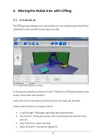
Page 17: ...the upper area the three ribbons Scene Motion and Programming provide access to the main functionalities On the left corner information on the robots current state are provided On the lower side four...

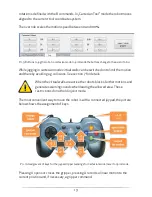
Page 18: ...ext menu Alternatively the function of the left mouse button can be changed in the upper menu area at Scene Navigation Possibilities are Selection Rotation Panning or Zooming 5 3 Moving the Robot The...

Page 19: ...thereby avoiding e g collisions See section 7 for details When the virtual walls are active the robots blocks further motions and generates warning sounds when leaving the allowed area These restrict...

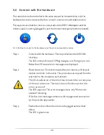
Page 20: ...e LED on the left side of CPRog changes color from grey to red Below the LED several error messages are displayed Step 2 Reset the errors This button resets the error memory of the joint module contro...

Page 21: ...s to be jogged into a perpendicular position using the joint mode The sticker on the axis provide assistance their triangles should be aligned with the structures marks The press the button Reset join...

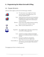
Page 22: ...ity Relative A linear motion with a defined distance starting at the current position Velocity in mm s Wait Waits for a time span defined in ms DigitalOut Sets a digital output The button on the left...

Page 23: ...till commands in the memory they can be deleted using the Delete button Afterwards linear joint gripper DOut and break commands can be recorded Pic 12 Buttons for program generation 6 3 Saving and Loa...

Page 24: ...a common elements are found Undo Redo and Load SaIve Two further buttons need explanaition The dust bin deletes the selected puzzle piece The light bulb updates the program on the current robot to the...

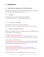
Page 25: ...robot further static active or mobile Objects can be added to the scene The following lines define these objects MovableSceneObjects NrOfObjects 1 MovableSceneObject0 Name Box Geometry Werkstueck obj...

Page 26: ...dware The control parameter of the joint controller can be adapted e g the position and velocity PID settings This can be done with the button Load Amp Config in the program start menu This button rea...

Page 27: ...IP Port When the ExternalMotion command is reached CPRog sends the current position in 20 Hz cycles to the server and expects the XYZABC set point velocity as answer o From the robot Pos 234 0 123 1 9...

Page 28: ...ion offers approaches to solve problems and errors in the areas Installation Software and Hardware If these measures do not solve your problem please get in contact with us we are happy to help Mail s...

Page 29: ...program see section 5 3 Avoid these problems by closing further programs eventually disabling the network connection and the virus scanner Does notmove any more Message Virtual Box violated and warnin...

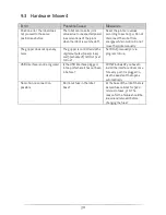
Page 30: ...more The gripper is controlled via the digital outputs 4 open close and 5 activated Is DOut5 set to true Set DOut 5 manually or via program to true USB Interface is not recognized Is the USB interfac...

Page 31: ...and Reference Linear Nr 2 x 232 93 y 12 2 z 494 01 a 0 05 b 84 25 c 0 vel 70 s t Descr Joint Nr 1 a1 5 19 a2 26 08 a3 124 72 a4 14 39 a5 0 a6 0 velPercent 35 Descr Relative Nr 17 x 0 y 0 z 20 0 a 0 b...

Page 32: ...Commonplace Robotics November 2012...

Reviews: