


Appendix B: Transmitter Installation
CommPact Installation Manual
106
Vibration Detector (EL-2607)
The EL-2607 is a wireless vibration detector that detects vibrations originating from a forced entry
attempt and offers adjustable sensitivity that can help to maximize detection whilst preventing false
alarms. The EL-2607 implements a feature designed to combat the problem of multiple
transmissions, which drastically reduce the life of the batteries. After an alarm transmission, there is
a four-minute delay during which further transmissions will not be sent.
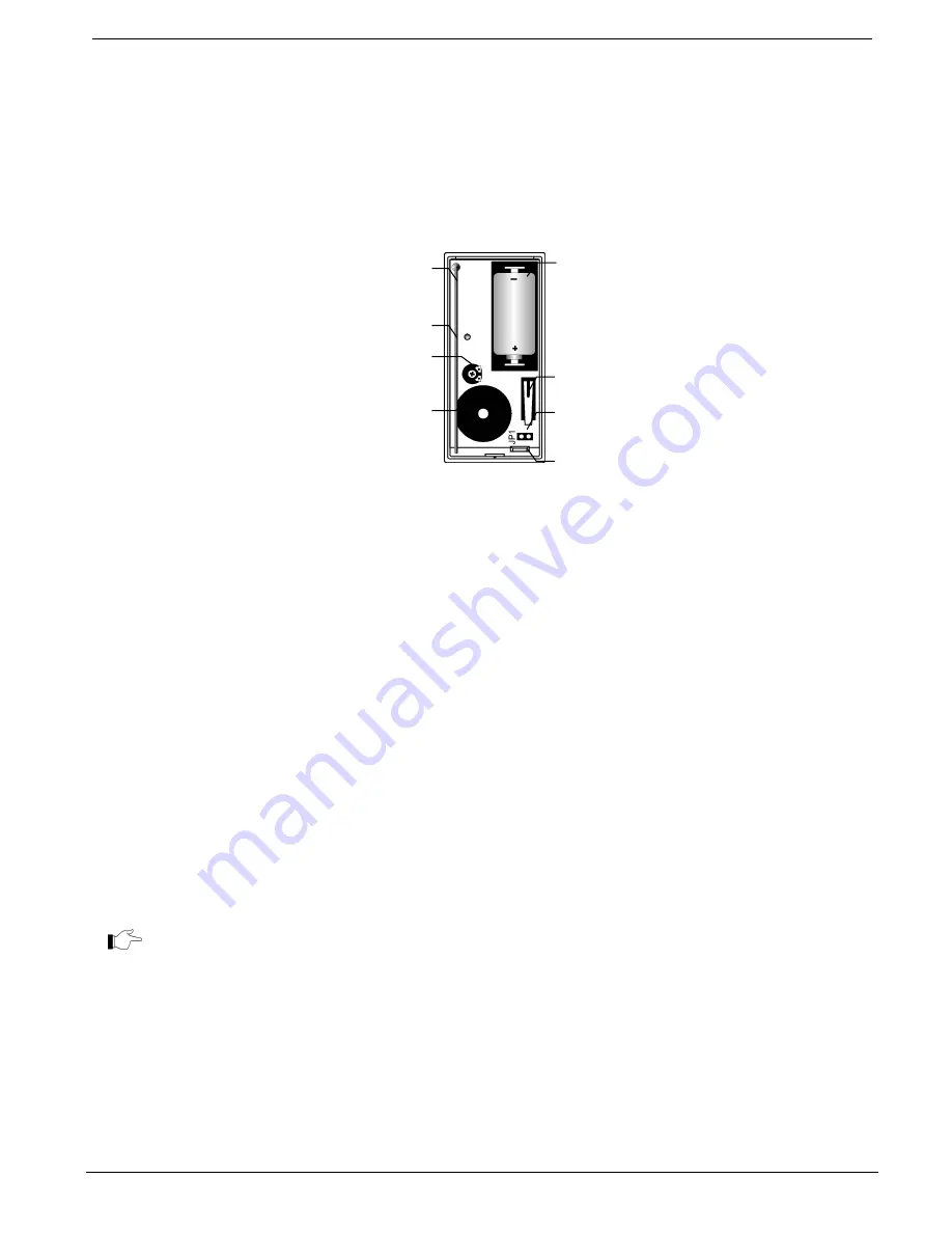
Figure B- 20: EL-2607 (Cover Off)
Installation Procedure
1.
To open the housing, insert a small screwdriver at the bottom of the unit between the
front and back cover and twist the screwdriver to release the cover.
2.
Remove the divider separating the battery from the contacts on the battery holder. When
you apply power and the Tamper switch is open, the EL-2607 enters Registration mode
during which a transmission is sent every few seconds. You can terminate Registration
mode by closing the Tamper switch. Test mode is automatically terminated after
approximately five minutes. Note: Due to the occurrence of voltage delay in lithium
batteries that have been in storage, the batteries may initially appear to be dead. In this
case, leave the unit in Test mode for a few minutes until the battery voltage level is
stabilized.
3.
While the EL-2607 is in Registration mode, set the receiver to Registration mode and
make sure that the transmitter’s LED indicator lights up at least twice. After registration,
momentarily close the Tamper switch to terminate Registration mode. Write the number
of the zone and the transmitter number (where applicable) on the sticker provided. Affix
the sticker inside the front cover for future reference.
The EL-2607 can also be registered to the receiver by manually entering the transmitter's
serial number.
4.
Before permanently mounting the unit, test the transmitter from the exact mounting
position. If necessary, relocate the transmitter to a better position.
5.
To remove the printed circuit board (PCB), press the PCB release tab, carefully lift the
board and slide it away from the back cover.
6.
The plastic housing can be screw mounted to doors and window frames or can be affixed
directly onto glass windows using a strong double-sided non-cushioned adhesive tape.
Mount the back cover and replace the PCB. Use two ISO 7050 (ST3.5 x 22) or similar
countersunk screws so that the screw head will not touch the PCB.
Battery
Holder
Tamper
Switch
PCB Release
Tab
Antenna
LED
Indicator
Sensitivity
Adjustment
Potentiometer
Piezo
Sensitivity
Adjustment
Jumper
Summary of Contents for Control system
Page 84: ...Appendix A Menu Structure CommPact Installation Manual 80 Appendix A Menu Structure ...
Page 85: ...Appendix A Menu Structure CommPact Installation Manual 81 ...
Page 86: ...Appendix A Menu Structure CommPact Installation Manual 82 ...
Page 87: ...Appendix A Menu Structure CommPact Installation Manual 83 ...
Page 88: ...Appendix A Menu Structure CommPact Installation Manual 84 ...
Page 89: ...Appendix A Menu Structure CommPact Installation Manual 85 ...
Page 90: ...Appendix A Menu Structure CommPact Installation Manual 86 ...


