1 Introduction
CommPact Installation Manual
5
1.4.1. Main
Board
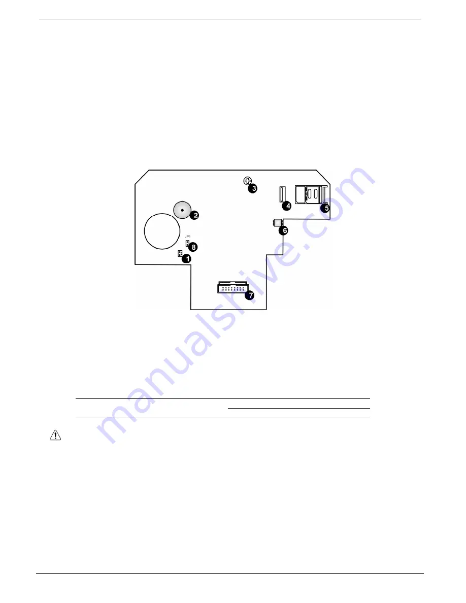
The Main Board is the brain of the system. It coordinates all the Control System activity.
The Main Board (see Figure
1-2) enables GSM and GPRS communication that allows reporting
events to the Central Station send or receive SMS messages, implement cellular Two-Way Audio
and remote software update.
This Board also has a standard dialer for communication via the Public Switched Telephone
Network (PSTN). Backup communication with event reporting, and Two-Way Audio (TWA) are
also available via PSTN.
The Main Board also has connectors to the Built-in Sounder and the Speaker.
Additionally, the Main Board includes a USB port for PC programming.
Figure 1-2: Main Board
1. Built-in Sounder Connector
2.
Buzzer
3. LCD Contrast Control
4.
USB Port
5. SIM-Card
Holder
6. Speaker
Connector
7. Flat-Cable Interface Connector to the Power Supply and
Connections Board
8.
Sounder Strength Control Jumper (JP1)
Table 1-2: Main Board Jumper Settings
JPI
Sounder Strength
(see Figure 1-2, Main Board)
Installed: 105dB
Removed: 85dB
Do not use VoIP phone lines for communication to the central monitoring station.
In certain cases the system may not transmit alarm signals successfully over the
VoIP network.
To reduce the risk of fire, use only No. 26AWG or larger telecommunication wire.
Flat cable (8) is not Removable!
Summary of Contents for Control system
Page 84: ...Appendix A Menu Structure CommPact Installation Manual 80 Appendix A Menu Structure ...
Page 85: ...Appendix A Menu Structure CommPact Installation Manual 81 ...
Page 86: ...Appendix A Menu Structure CommPact Installation Manual 82 ...
Page 87: ...Appendix A Menu Structure CommPact Installation Manual 83 ...
Page 88: ...Appendix A Menu Structure CommPact Installation Manual 84 ...
Page 89: ...Appendix A Menu Structure CommPact Installation Manual 85 ...
Page 90: ...Appendix A Menu Structure CommPact Installation Manual 86 ...


