background image

www.commscope.com 


860479229 

Issue 7, May 2013 


Page 3 of 15 

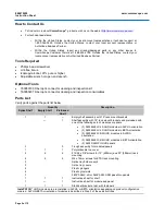
Separately Orderable Modules and Panels 

Material ID 

Part No. 

Description 

760111013 

360-3M-4MPM1-48LC-LS 

InstaPATCH 360 

UHD

 LazrSPEED

® 

MM module, 48F LC 

760111039 

360-3M-4MPM1-48LC-TS 

InstaPATCH 360

 UHD 

TeraSPEED

® 

SM module, 48F LC  

760111153 

3603P-24MPO 

UHD distribution adapter panel, 24xMPO 

760111088 

360P3-48LC-LS 

UHD pass-thru panel, 48xLC 

LazrSPEED

 adapters 

760111104 

360P3-48LC-SM 

UHD pass-thru panel, 48xLC 

TeraSPEED

 (SM) adapters 

Accessories 

Material ID 

Part No. 

Description 

760112003 

CMS-2-02 

Fiber cord management sleeve 

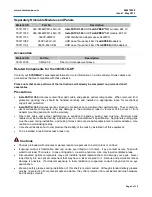
Related Components for the 3603D-1U-UP 

Contact your 

SYSTIMAX

 sales representatives for more information on a wide variety of trunk cables and 

accessories that are compatible with these shelves. 
 

Please note that some portions of the instructions will already be completed on preloaded shelf 
assemblies

Precautions 


InstaPATCH


360 

modules contain fiber optic cable and passive optical components.  When removed from 

protective packing, they should be handled carefully and installed in appropriate racks for mechanical 
support and protection. 


InstaPATCH


360

 modules require virtually no maintenance to maintain their performance.  They contain no 

user-serviceable components, and any damage to the anti-tamper label or removal of top cover or front 
adapter mounting panel will void the warranty. 


Fiber optic cable and jumper performance is sensitive to bending, pulling, and crushing.  Minimum bend 
radius must be maintained during installation per the manufacturer’s specification.  Appropriate pulling grips 
must be used during installation, and pulling forces shall not exceed manufacturer’s recommendations.  Use 
caution to avoid kinking cables.


Care should be taken not to compromise the stability of the rack by installation of this equipment.


To be installed in restricted access areas only.


 Cautions


Shelves preloaded with modules or panels require two persons to install to rack or cabinet. 


Isopropyl  alcohol is flammable, and can cause eye irritation on contact.  If eye contact occurs, flush with 
water for at least 15 minutes.  In case of ingestion, consult a physician.  Use only in well ventilated areas 


Disconnected optical components may emit invisible optical radiation that can damage your eyes.  Never 
look directly into an optical component that may have a laser coupled to it.  Serious and permanent retinal 
damage is possible.   If accidental exposure to laser radiation is suspected, consult a physician for an eye 
examination. 


Wearing safety glasses during installation of this shelf is recommended.  Although standard safety glasses 
provide no protection from potential optical radiation, they offer protection from accidental airborne hardware 
and cleaning solvents. 

Summary of Contents for 3603D-1U-144LC-LS-A

Page 1: ...BETA orientation or panels Additional shelf configurations provide for fusion splicing when using LC pass thru panels Ordering information is listed below Material ID Part No Description 760110999 3603D 1U UP Fiber shelf 1U UHD empty 760136457 3603D 1U 144LC LS A 3603D 1U UP UHD shelf with three 3603M 48LC LS UHD modules in ALPHA orientation 760136465 3603D 1U 144LC LS B 3603D 1U UP UHD shelf with...

Page 2: ... parts against the parts list below Quantity Description Splice Shelf Empty Shelf Preloaded Shelf 1 1 Empty shelf assembly with 19 rack mount brackets 1 Shelf assembly with 19 rack mount brackets and preloaded with one of the following sets of modules or panels 3 3603M 48LC LS UHD modules in ALPHA orientation 3 3603M 48LC LS UHD modules in BETA orientation 3 3603M 48LC SM UHD modules in ALPHA orie...

Page 3: ...the anti tamper label or removal of top cover or front adapter mounting panel will void the warranty Fiber optic cable and jumper performance is sensitive to bending pulling and crushing Minimum bend radius must be maintained during installation per the manufacturer s specification Appropriate pulling grips must be used during installation and pulling forces shall not exceed manufacturer s recomme...

Page 4: ...abinet Mount Caution Preloaded shelf configurations require two people for installation in equipment rack 1 Determine desired mounting location in 19 483mm rack or cabinet 2 Mount shelf to rack or cabinet using pre installed mounting brackets and four 12 24 x 3 8 screws or four M6 screws provided 3 Mount rear stabilizer brackets to rack cabinet with four 12 24 screws or four M6 screws as shown Mou...

Page 5: ...shelf fully extended Cable tie or hook and loop strip 3 76mm below shelf Cable ties or hook and loop strips installed on outside of shelf slide Note This shelf is designed for direct connection of cables using cable glands inserted into cable entry ports as shown above Another method for securing cables is the use of optional rack mounted brackets See instruction sheet 860380781 for using rack mou...

Page 6: ...it to pass through selected opening and enter shelf Note It may be necessary to temporarily remove a plug from an adjacent opening to provide sufficient clearance for gland nut to be inserted through opening 8 Insert threaded body of cable gland into opening and tighten gland nut onto threaded section to secure cable gland unit to shelf Note The two recommended methods Method A and Method B for ro...

Page 7: ...and loop strip 3 Verify that shelf retracts and extends fully before proceeding Slack loop in cables with shelf in retracted position Method A Cable ties or hook and loop strips Method B Shelf fully retracted 4 The above figure shows typical fiber loop for both Method A and Method B fiber routing when shelf is retracted Step 2B Routing Multiple Cables into Sliding Shelf Method A Shown Cabe entry p...

Page 8: ...79 provided with the modules Note InstaPATCH 360 UHD modules must be configured as shown below for proper polarity Identical modules are used at both ends of cable but module orientation is inverted from end to end Module at one end of trunk cable must be oriented in ALPHA configuration while module at opposite end of cable must be oriented in BETA configuration Preloaded shelves come with modules...

Page 9: ...elf so that the pivot lock pin is in back of the pivot bracket Note Panel module pivot lock pin can only be inserted from the rear of pivot mounting bracket 3 Depress the lever arm on the pivot mounting bracket and slide panel module forward until pivot lock pin engages the hole in pivot mounting bracket 4 Release lever arm of pivot mounting bracket to secure the panel module in place Subsequent p...

Page 10: ...e with Mille Ties or hook and loop fastener strips 3 Install MPO connections to InstaPATCH modules plug each MPO connector into back of module as shown above LC Ports 1 6 MPO Port 1 LC Ports 7 12 MPO Port 2 LC Ports 13 18 MPO Port 3 LC Ports 19 24 MPO Port 4 Note Use triangular holes in bottom of shelf tray to gain better access to bottom module MPO connections Step 6 Install Cover 1 Remove protec...

Page 11: ... clamps on trough and install hook and loop fastener around patch cords and through slots at trough exit 4 Place fiber patch cords into management sleeve wrap and fasten hoop and loop fastener running the length of Management Sleeve 5 The Management Sleeve may be additionally tied off in rack or cabinet vertical by using the rear webbings and cable ties Management sleeve may be route up down or st...

Page 12: ...ed for optional mounting scheme 4 positions Buffer tube tie down rail 4 positions Splice sleeve holders 2 Positions External buffer tube tie down points 6 positions Cover retention snaps 6 positions Fiber retention gate 2 positions Retention slots 6 positions Top cover Snap rivet grommet 4 positions Snap rivet plunger 4 positions Note Snap rivet grommets and plungers are not used for single tray i...

Page 13: ... the same length and to enter shelf in the same location to facilitate manageable spooling of slack loop into shelf for tray installation Keep buffer tubes on rearward facing side of splice tray so as to keep patchcord exit ports as unobstructed as possible Use cable ties provided to restrain buffer tubes to tie down rails on tray Tray is designed for 3mm and 4mm buffer tube diameters Larger diame...

Page 14: ...n tray and fiber as desired UHD positioning is shown above into shelf Remove paper backing from splice tray and press down on tray firmly at several locations around its perimeter to insure that adhesive contacts shelf surface as desired 3 Spool buffer tube slack behind tray and use cable ties to attach it at the external buffer tube tie down points as required 4 Terminate pigtails into adapters 5...

Page 15: ...rms of previous tray Additional trays must be rotated 180 from the previous tray orientation 2 Install snap rivet grommets and plungers 3 Install top cover 4 Repeat as required Note Three trays may be used in a 1U shelf for a total of 144 fusion splices Six trays may be used in a 2U shelf for a total of 288 fusion splices and twelve trays may be used in a 4U shelf for a total of 576 fusion splices...

Reviews: