
www.commscope.com
860479229
Issue 7, May 2013
Page 5 of 15
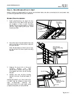
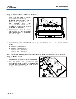
2 Post Rack Mount
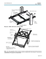
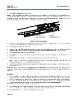
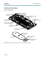
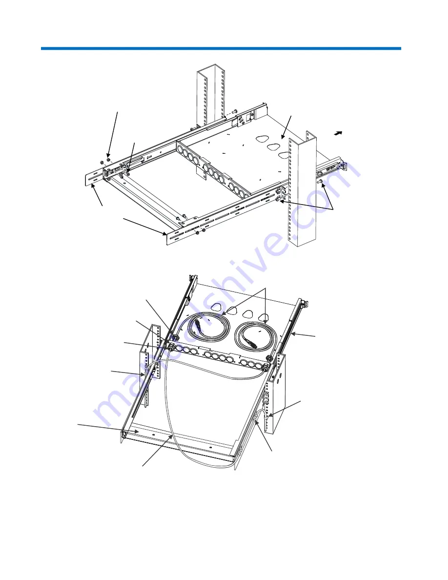
Step 2A – Route and Secure Cable to Shelf
Method A
Cable looped to shelf slide
on opposite side of panel from
entry point into shelf
Fiber management
bar
Method B
Cable dressed
over shelf slide
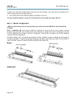
Cable
gland
Cable entry
port
Gland nut
(inside of shelf)
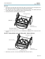
Store slack fiber in shelf
Sliding shelf
fully extended
Cable tie or hook-and-loop
strip 3” (76mm) below shelf
Cable ties or hook-and-loop strips
installed on outside of shelf slide
Note:
This shelf is designed for direct connection of cables using cable glands inserted into cable entry ports as
shown above. Another method for securing cables is the use of optional rack mounted brackets. See instruction
sheet 860380781 for using rack mounted brackets.
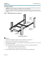
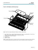
Front
12-24
screws
(8 places)
8-32 nuts with lockwashers
(4 places)
8-32 screws
with lockwashers
(4 places)
3603D-UDH-1U shelf
Rear stabilizer
brackets