

860479229
Instruction Sheet
www.commscope.com
Page 6 of 15
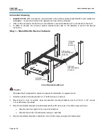
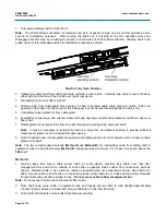
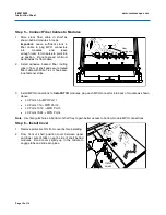
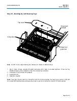
1. Fully extend sliding shelf to front of rack.
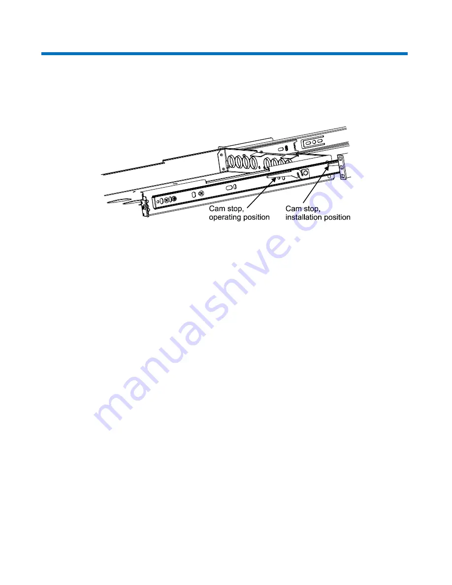
Note
: The shelf sliding mechanism incorporates two sets of position stops: one for normal operation and a
second for installation purposes. When pulling the shelf out, it will stop at the first operation cam stop.
Disengage this first stop by actuating the levers on both sides of shelf slide mechanism, allowing shelf to be
pulled out to its fully extended position for installation purposes as shown.
Shelf in Fully Open Position
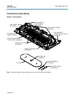
2. Cables may enter shelf from either right side, left side, or rear apron. Carefully loop cable to rear of shelf on
either side and continue to feed cable over top of rear apron.
3. Temporarily store slack fibers in shelf.
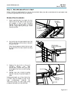
4. Remove plug from appropriate size opening in shelf to accommodate cable gland on cable. Select an
opening on rear apron or either right or left side panel that will be most advantageous for cable entry.
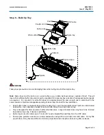
5. Completely loosen gland nut from cable gland.
6. Feed MPO connector(s) and subunit tube(s) through opening in shelf and temporarily coil fibers loosely in
fiber shelf.
7. Rotate gland nut as required to allow it to pass through selected opening and enter shelf.
Note:
It may be necessary to temporarily remove a plug from an adjacent opening to provide sufficient
clearance for gland nut to be inserted through opening.
8. Insert threaded body of cable gland into opening and tighten gland nut onto threaded section to secure cable
gland unit to shelf.
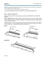
Note:
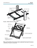
The two recommended methods (
Method A
and
Method B
) for routing fiber cable from sliding shelf to
equipment rack are described below.
Method B
routing requires a minimum of 1U open rack space above the
360
shelf.
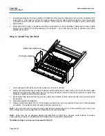
Method A
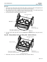
1. Working back from where cable enters shelf (at cable gland), carefully loop cable over rear fiber
management bar and then to outside of shelf slide on opposite side of panel from cable entry point as
shown. Maintain cable in as small of a radius as possible while not exceeding minimum bend radius for
cable. Secure cable to shelf slide in at least two places using cable ties or hook-and-loop strips threaded
through slots and punches provided in rails.
Do not secure cable to fiber management bar.
Note:
Do not exceed minimum bend radius for fiber cable.
2. From shelf slide, route cable to equipment rack and loosely secure cable to rack upright approximately
3 inches (76mm) above or below shelf, using a cable tie or hook-and-loop strip.
3. Verify that shelf retracts and extends fully before proceeding.


