ADCP-90-606 • Rev C • May 2020
Page 22
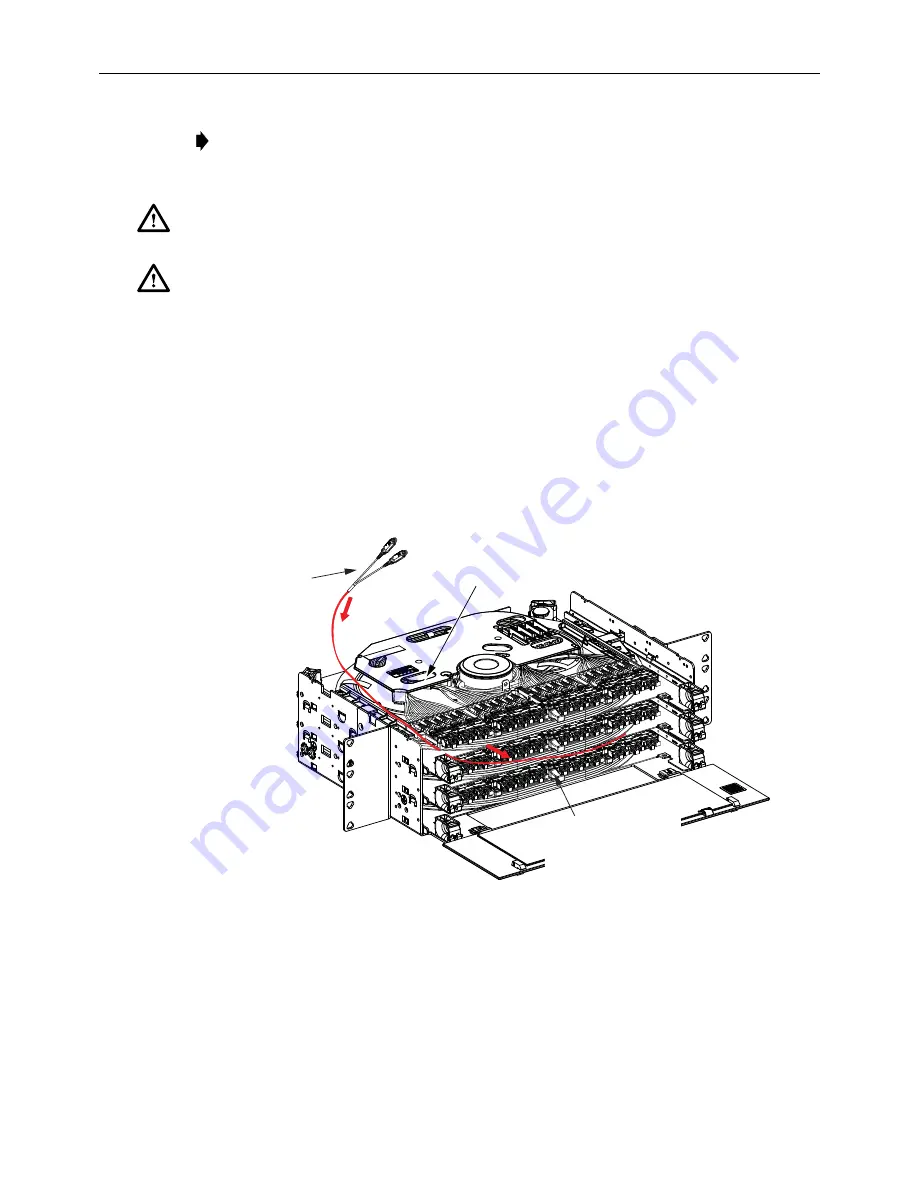
7. To re-route a cable with MPO connectors or a stub end with non-functional connectors to
the front of the panel:
a. Pull out enough microcable to rotate the internal spool 90º as shown in
.
b. Remove the microcable from the rear cable retainer and then push the connectors back
into the space between the left side of the panel and the bulkhead panel. This will form
a slack loop at the front of the panel.
c. Pull on the slack loop to draw the connectors through to the front.
Figure 23. Pulling Microcable to the Front of the Panel Shell for Front Routing
8. To re-route a cable with fanout assemblies (with individual connectors) or cabled modules
to the front of the panel:
a. Remove the #4-40 bonding screws located on either side of the panel shell at the
points indicated in
. Save screws for reuse.
Note:
Provide at least 3 inches (7.6 cm) of clearance at the rear side of the panel to allow
the spool to rotate freely as the microcable is unwound.
Caution:
Avoid using excessive force when unwinding microcable from the internal spool. Use
the hand-wrap method (see
) if pulling on the cable by hand.
Caution:
If the cable fails to unwind, check for obstacles or obstructions that would prevent the
spool from turning. The maximum recommended pull force that may be applied to the MPO
connector pulling eye, fanout assembly pulling sock, stub connector pulling eye, or to the cable
itself is 40 lbs. (18.14 kg)
.
CONNECTORS
NOTE: TOP REMOVED TO SHOW
CABLE SPOOL TRAY AND
MICROCABLE ROUTING DETAIL
26199-A
STEP
b
PUSH MICROCABLE INTO
PANEL SHELL TO FORM SLACK
LOOP AT FRONT OF PANEL
STEP
a
ROTATE SPOOL UNTIL BULKHEAD
IS ALIGNED AS SHOWN
STEP
c
PULL ON SLACK LOOP
TO DRAW CONNECTORS
TO FRONT OF PANEL


