408-32067
2
of 4
Rev
B
— INSPECT BEFORE YOU CONNECT!
Before inspecting a fiber endface, DISCONNECT the
optical fiber from the power signal source. Always
clean and inspect a fiber endface before installing and
connecting the cable assembly.
— NEVER inspect the fiber endface when power is
applied to the optical fiber.
4. INSTALLATION PROCEDURE
4.1. Tools
The followings tools are needed for installation:
DANGER
STOP
— MTP/MPO In Bulkhead Adapter Cleaner 1918809-1
— LC/SC In Bulkhead Adapter Cleaner 2064500-1
— One Slot Reel Cleaner 1918803-1
(for MPO connectors and LC connectors)
— 200× Microscope Kit 1754767-1 fitted with:
— Universal Microscope Adapter 1754765-1
(for LC connectors)
— MPO Microscope Adapter 1828836-1
(for MPO multimode connectors)
— MPOA Microscope Adapter 1828837-1
(for MPO singlemode connectors)
To avoid personal injury, NEVER view an active
optical fiber using a microscope.
NOTE
i
Professional Fiber Optic Connector Inspection Kit
2064651-1 contains all of the above tools.
— cross-recessed screwdriver
4.2. Preparation
Before beginning installation:
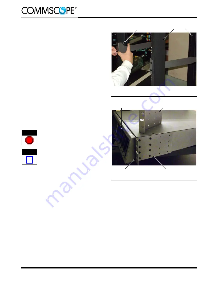
Rails of Rack (Ref)
Long Cutout of Bracket
Facing Up
— The enclosure must be installed directly below
the switch (no gap).
— If desired, remove the rear brush from the
chassis; the rear brush cannot be removed after
the enclosure is mounted onto the rack or cabinet.
4.3. Mount the Enclosure
1. Determine the vertical and horizontal (flush or
protruding) mounting position of the enclosure in the
rack or cabinet.
2. Using 4 of the 12-24 UNC-2A screws, install the 2
rear brackets onto the rack or cabinet (2 screws per
bracket, 1 bracket per side of rack or cabinet).
Observe the arrow and “TOP” marking on each
bracket (shown in Figure 1) for correct orientation
for installation (the long cutout of the bracket should
be facing up). See Figure 2. DO NOT tighten the
screws at this time.
Figure 2
Front Bracket Not Installed
on Chassis (Ref)
Openings for Adapter Plates
(Front of Chassis)
Front Bracket Installed on Chassis
(In Flush Mounting Position, Ref)
Short Leg of Bracket
Facing Forward
Figure 3
3. Using the 6-32 UNC-2A screws, install the 2 front
brackets onto the chassis (8 screws per bracket, 1
bracket per side of chassis). Make sure that the
short leg of each bracket is facing forward. Tighten
the screws. See Figure 3.
4. Align the back of the chassis with the back of the
legs of the rear brackets. Slide the chassis through
the rails of the rack or cabinet and onto the legs.
Make sure that the legs enter the guide channels on
each side of the inside of the chassis. See Figure 4.
5. Insert 4 of the 12-24 UNC-2A screws through the
holes in the front brackets (2 screws per bracket),
and secure the front brackets to the rack or cabinet.
See Figure 5, Detail A.
6. Tighten the screws of the rear brackets to secure
the rear brackets to the rack or cabinet. See Figure
5, Detail B.


