
408-3128
2
of 3
Rev
D
Refer to 408-10267, included with the tool, for
instructions on how to use the tool.
It is
recommended not to use any other crimping
method.
a. Crimp one end of the splice connector onto
one end of the cable.
b. Crimp the other end of the splice connector
onto the other end of the cable.
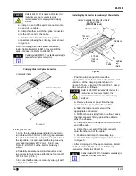
c. Position and crimp the remaining splice
connectors following the crimping order shown
in Figure 3.
6. After crimping all of the splice connectors,
install Cable Insulator 556411-1 over all of the
splice connectors. Refer to 408-3218.
Cable Insulator 556411-1 (available separately) is
required for all splice connectors.
Figure 3
3.2. Tap Connector
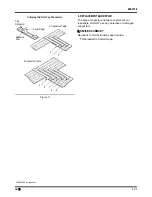
1. Align the tap cable perpendicular to the main
run cable with a 3.18-mm [.125-in.] gap between
the cables. Fold back the top blue vinyl shield of
the tap cable. Cut and separate the top blue vinyl
only (approximately 457.2 mm [18 in.]). See
Figure 4. DO NOT cut the bottom blue vinyl
shield.
2. Carefully separate the main conductors and
tap conductors along the perforations for a length
of 152.4 mm [6.0 in.].
3. Ensure that the cable is clean by wiping it with
a dry, clean, soft cloth.
Figure 4
4. Position a tap connector around the
appropriate conductor on each cable starting with
position 1 of the crimping order shown in
Figure 5. Then, using Hand Tool 91392-1, crimp
the connectors as follows.
Refer to 408-10267, included with the tool, for
instructions on how to use the tool.
It is
recommended not to use any other crimping
method.
a. Remove the cover paper from the tap
connector to expose the adhesive film.
b. Slide the tap connector around the
appropriate conductors.
c. With both cables lying flat on the floor, press
the tap connector firmly against the cable to
affix the adhesive.
d. Crimp one end of the tap connector onto one
end of the cable.
e. Crimp the other end of the tap connector
onto the other end of the cable.
f. Position and crimp the remaining tap
connectors following the crimping order shown
5. After crimping all of the tap connectors, install
Cable Insulator 556411-1 over all of the tap
connectors. Refer to 408-3218.
Cable Insulator 556411-1 (available separately) is
required for all tap connectors.
!
CAUTION
NOTE
i
1
2
3
4
5
Crimping Order for Splice Connectors
3
1
2
5-Conductor Cable
3-Conductor Cable
3.18-mm
[.125-in.]
Gap
Main Run Cable
Cut and Separate Top Blue Vinyl Shield
457.2 mm [18 in.]
(DO NOT Remove)
Tap
Cable
Fold Back
152.4 mm
[6.0 in.]
Top Blue
Vinyl
Shield
!
CAUTION
NOTE
i
Installing Tap Connector to Undercarpet Power Cable


