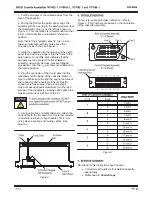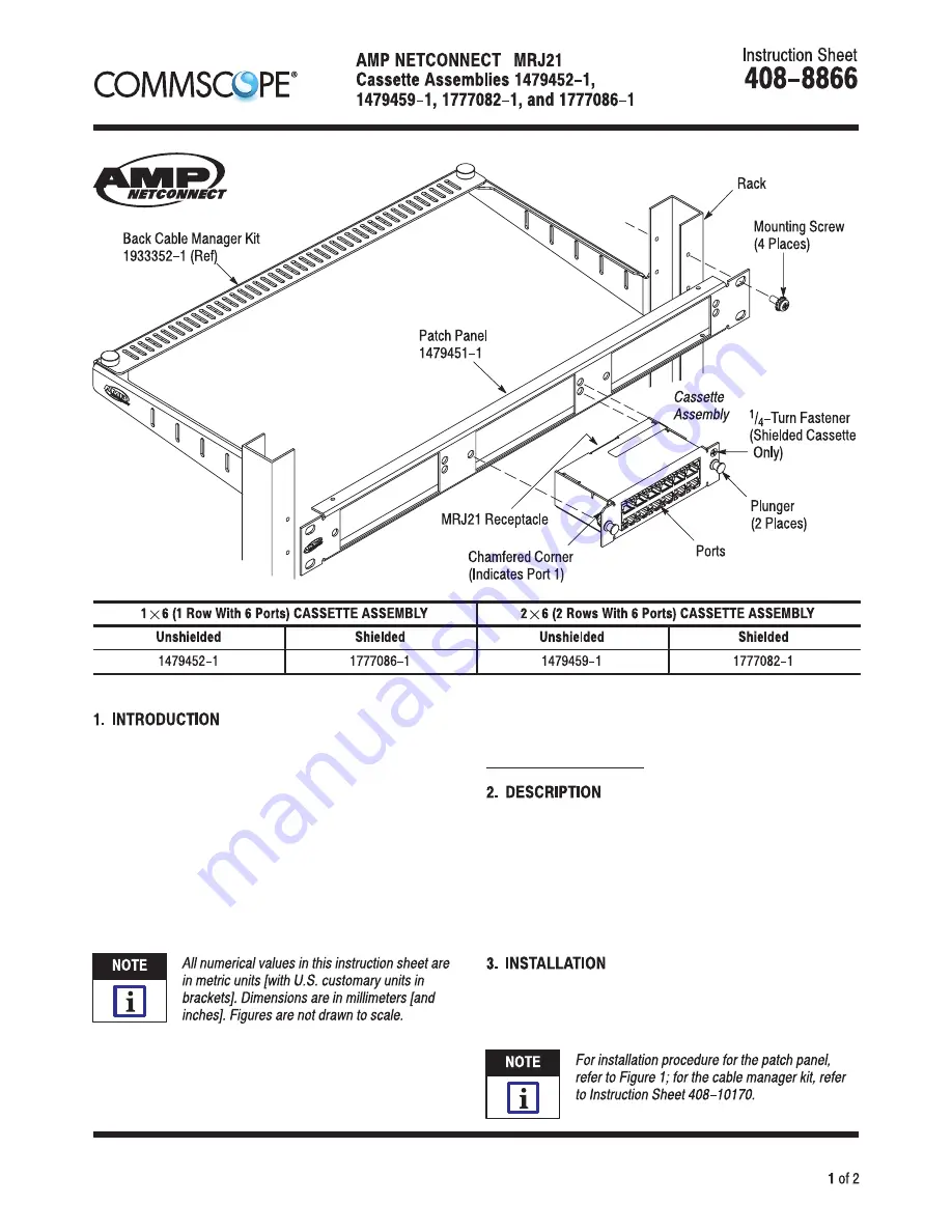
Figure 1
MRJ21 cassette assemblies listed in Figure 1 are
designed to be installed into Patch Panel 1479451–1.
Back Cable Manager Kits 1933352–[ ] (shown in
Figure 1) can be used to support the trunk cable. The
patch panel and cable manager kit are designed to be
mounted onto a standard 483–mm [19–in.] Electronic
Industries Alliance (EIA) rack or equipment cabinet.
Read these instructions thoroughly before starting
installation.
Reasons for reissue of this instruction sheet are
provided in Section 5, REVISION SUMMARY.
The front of each cassette assembly features two
plungers used to secure the assembly to the patch
panel and a chamfered corner that indicates Port 1.
The shielded cassette also has a
1
/
4
–turn fastener
used for bonding. The back of each cassette
assembly features an MRJ21 receptacle that accepts
the connector of the trunk cable. See Figure 1.
Using the mounting screws, mount the patch panel
and cable manager kit onto the rack, then proceed as
follows:
© 2016 CommScope, Inc.
All Rights Reserved
To obtain information on
CommScope
®
products,
contact your local
CommScope
®
account
representative, PartnerPRO
™
Network Partner
or visit our website at www.commscope.com
This product is covered by one or more U.S.
patents or their foreign equivalents. For patents, see
www.commscope.com/ProductPatent/ProductPatent.aspx
Dec. 2016 Rev G
®
™
™
To obtain information on
CommScope
products, visit the CommScope website at
www.commscope.com


