408-8398
2
of 2
Rev
D
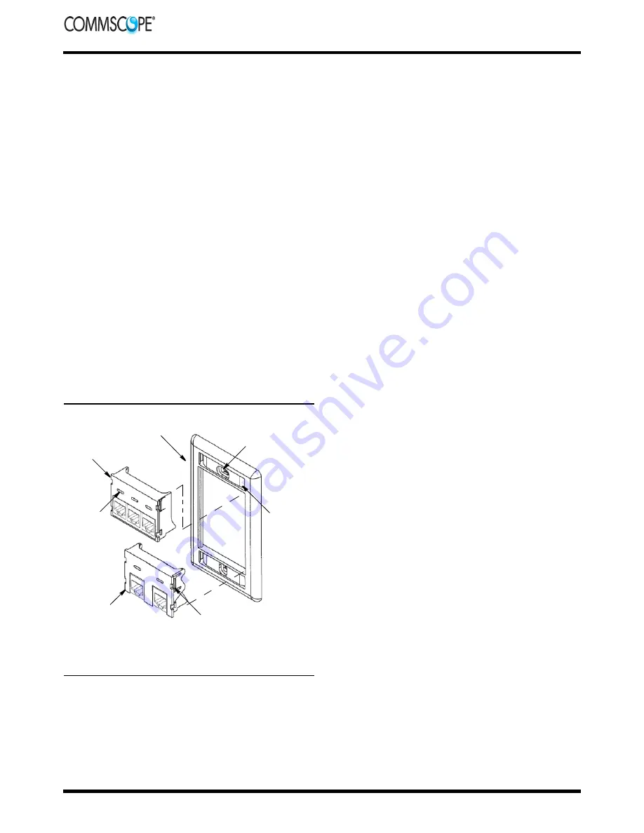
3.3. Insert
(See Figure 2)
1. Install the proper connection to the rear of the
insert.
2. Align the insert with the back of the selected
module.
3. Install the insert at a slight angle with the
stationary latch on the rail of the module. Gently
pivot the insert until the movable latch engages
onto the opposed rail and snaps into place.
4. Install blank inserts into the ports that are not
used.
3.4. Module
1. From the front of the faceplate, position the
loaded module in the port and snap it into place.
Repeat this step as needed.
2. Install blank modules (1.5 or 1 unit high) into
the faceplate where loaded modules are not
used.
3. Secure the faceplate to the box by installing
and tightening the mounting screws.
4. Install the label and label cover into the label
holder. If applicable, install standard icons into
the flashed-over icon slots (not included).
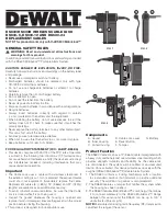
Figure 3
4. REMOVAL
4.1. Module
To remove a module from the faceplate:
1. Insert a screwdriver tip into the module
removal access hole (upper latch on 1.5 unit high
and lower latch on 1 unit high, refer to Figure 3)
and gently release the latch.
2. Using the screwdriver tip in the remaining
access holes, gently remove the module from the
faceplate.
4.2. Jack and Insert
To remove a jack or insert from the module:
1. Insert a screwdriver tip over the moveable
latch and pry down slightly to release the latch.
2. Pull the jack or insert out of the module.
5. REVISION SUMMARY
Revisions to this instruction sheet include:
•
Changed company logo
•
Updated instruction sheet to corporate
requirements
•
Added AMP NETCONNECT logo and website
•
Rebranded to CommScope
Module
(Ref)
Mounting Screw
Hole (Ref)
Front of
Faceplate
Icon Slot
Label
Holder
Module
(Ref)
Module Removal
Access Hole (Ref)
Note:
For clarity, cables are not shown.


