


Page 4 of 8
© 2019 CommScope, Inc. All Rights Reserved
8.3.
Armored Feeder Cable Preparation
8.3.1.
Prepare cable:
Ribbon fiber length:
76”
(length from ring cut to end of
ribbons).
Central core tube length:
45”
(ring cut to end of core tube).
8.3.2.
Bond cable and attach strength members per
diagram on packet of 4460D\FO bond clamp kit.
8.3.3.
For feeder cable installation refer to Section 8.2.2
through 8.2.6 to proceed.
8.3.4.
Attach ground wire per grounding kit installation
instructions.
8.4.
Fiber Routing and Splicing
8.4.1.
Remove
splitter with mounting plate
and set aside
to gain access to splice tray. Lift the top cover of the tray to
make the splice holder accessible.
8.4.2.
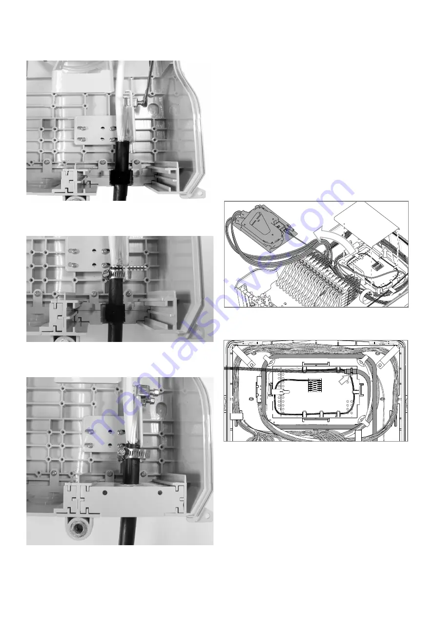
Route central core tube to splice tray and attach
with felt tape and cable ties (see illustration below).
8.4.3.
If existing core tubing needs to be replaced, cut
central core tube to a length of 4”.
8.2.4.
Attach cable strength member to strength member
bracket with supplied strength member lug.
Note:
Check the seal foam around the cable that it falls into
the cavity of the entry plate.
8.2.5.
Attach cable directly to strain relief bracket with
supplied hose clamp as shown.
Note:
Leave some clearance
between jacket end and hose clamp.
8.2.6.
Reassemble the cable seal plates.
Note:
The foam on the cables should be sandwiched
between the back and middle entry plates to create a seal.


