TECP-91-008 • Rev C • January 2019
Page 20
© 2019
CommScope
. All Rights Reserved.
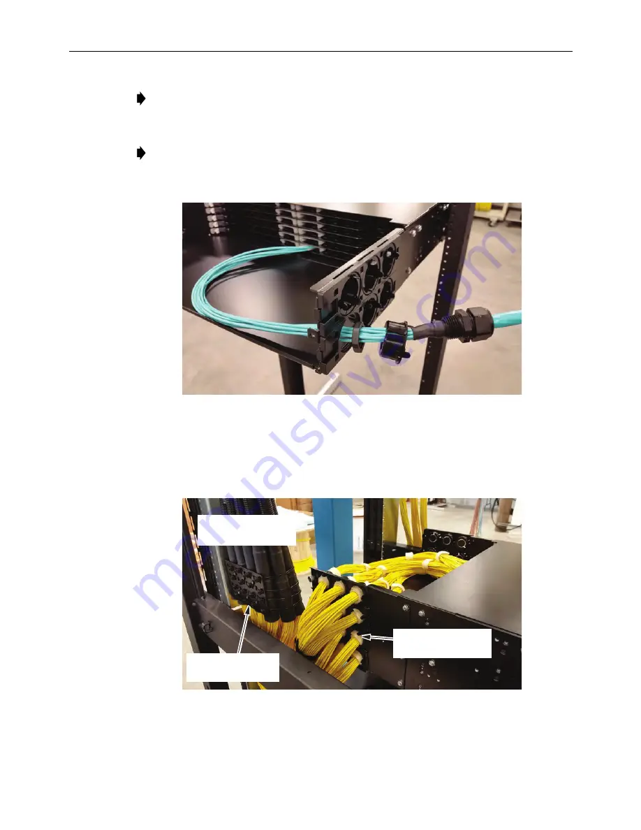
Figure 24. Routing in the First Trunk
(Trunk With Gland Adapter Shown)
6. Continue routing in trunks and plugging in connectors, referring to
Figure 25
,
Figure 26
, and
Figure 27
.
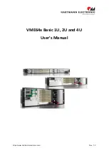
Figure 25. Trunk Routing Into Side of Panel
(Trunk With No Gland Adapter Shown)
Note:
Hook-and-loops should be installed around bundles for each tray. Install
where bundle begins to spread out naturally due to routing lengths. Refer to
Figure 21 on Page 18
.
Note:
Breakout lengths for trunks entering panel from side plates should be 30+/-
3 in. (76.2+/-7.62 cm). CommScope trunk cables with gland adapters meet this
requirement.
CABLES SECURED
TO CABLE BRACKET
(ACCESSORY EHD-CMB)
NOTE: HOOK AND LOOP
AROUND BREAKOUTS AS
THEY ENTER CHASSIS.
26428-A
NOTE: TRUNKS SHOWN
IN THIS FIGURE DO NOT
HAVE GLAND ADAPTER.


