TECP-91-008 • Rev C • January 2019
Page 4
© 2019
CommScope
. All Rights Reserved.
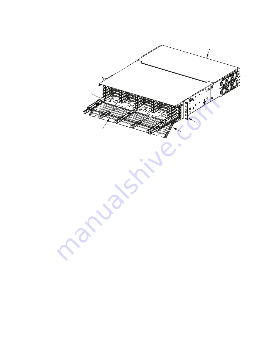
Figure 1. EHD Panel Main Components (2U Model Shown)
•
Rear Cover—
can be removed to allow a blade to be removed from the rear of the
panel. It is also removed to route in and secure fiber cables on the rear of the
panel.
•
Grounding Location—
is where a two-hole lug (not provided) and ground wire
are attached to connect the panel ground PEM nuts to office ground. The two-hole
lug to be used requires a spacing between holes of 0.625 inch (1.59 cm).
•
Mounting Brackets—
can be flipped around to provide either front- or rear-facing
mounting on a channel rack. The mounting brackets can be mounted with a
recess of either 3 inches (7.62 cm) or 6 inches (15.24 cm).
•
Front Door—
swings down to provide access to the interior of the panel. The door
features a double-hinged design that allows users to open the door without
interfering with equipment below the panel on the same rack, or to move the door
into its lower position allowing the lowest blade to open freely.
•
Designation Label—
provides physical space for recording fiber designations.
1.3
Comparative View of 1RU, 2RU, and 4RU Panel
The figures below provide comparative views of the different sizes of the EHD Panel,
as follows: 1RU panel (
Figure 2
); 2RU panel (
Figure 3
); 4RU panel, front view
(
Figure 4
); 4RU panel, rear view (
Figure 5
).
Figure 6
shows the rear of the 4RU panel
with rear cover removed. The 4RU panel has a removable mid-shelf, also shown in
Figure 6
.
26418-A
MOUNTING
BRACKET (2X)
BLADE
(PARTLY REMOVED
FROM CHASSIS)
DESIGNATION LABEL
FRONT
DOOR
GROUNDING
LOCATION
REAR
COVER


