TECP-91-008 • Rev C • January 2019
Page 8
© 2019
CommScope
. All Rights Reserved.
5. Save all shipping containers for use if the equipment requires shipment at a future
date.
3
PANEL INSTALLATION
3.1
Overview
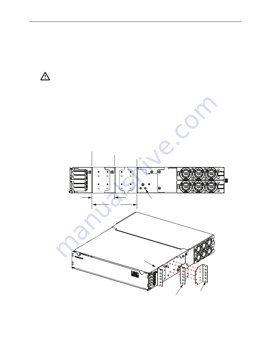
The EHD Panel, shown in
Figure 7
, is mounted in a 19 inch (48.26 cm) channel rack or
cabinet. When mounting into a cabinet, it is recommended that the rear mounting rails
be 24 inches back (60.96 cm) from the front mounting rails. Trunk breakouts are
intended to come into the rear right or left side of the panel. CommScope trunks with
standard breakouts and gland adapters are the preferred method.
If required per local standards, the panel can be grounded as described in
Section 3.3
on Page 10
. Ground lugs and ground cables are not provided with the panel.
Figure 7. Mounting Options
Caution: This equipment is to be installed only in Restricted Access Areas (dedicated
equipment rooms, equipment closets, etc.).
26405-B
3.0 IN.
(76.2 CM)
6.0 IN.
(152.5 CM)
RIGHT SIDE VIEW
OF CHASSIS
FRONT OBLIQUE VIEW
OF CHASSIS
MOUNTING POSITION FOR FRONT OF 3-INCH CHANNEL
MOUNTING POSITION FOR BACK OF 3-INCH CHANNEL
MOUNTING POSITION FOR BACK OF 6-INCH CHANNEL
MOUNTING POSITION
FOR FRONT OF
3-INCH CHANNEL
MOUNTING POSITION FOR
BACK OF 3-INCH CHANNEL
MOUNTING POSITION
FOR BACK OF
6-INCH CHANNEL
MOUNTING LOCATION
FOR GROUND LUG
(OPTIONAL)


