Era
™
Medium Power Carrier Access Point Installation Guide
M0201AJB
Page 48
© October 2018 CommScope, Inc.
Installing CAP Ms
Connect the CAP M to an RF Antenna
1
Obtain 50
Ω
coaxial cables that are of sufficient length to reach from the CAP M to the passive antenna. The
end of the 50
Ω
coaxial cable that will connect to the ANT connector can be either a push-pull connector
or a threaded connector.
2
Install the passive antennas per the manufacturer’s installation instructions.
3
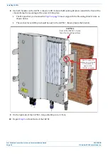
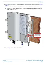
Remove the IP67/EMI blank plug from the ANT connector.
4
Connect the passive multi-band antenna to the ANT connector using coaxial cable with the least amount
of loss possible.
•
If the 50
Ω
coaxial cable has a push-pull connector, make sure the cable is seated firmly in the ANT
connector.
•
If the 50
Ω
coaxial cable has a threaded connector, torque the connector 5 N-m (3.69 ft-lb). Do not
over-tighten the connector.
5
Connect the other end of the 50
Ω
coaxial cable to the passive antenna installed in
Connect the CAP M to a Classic CAN or TEN
Connect the CAP M Optical Port 1 as appropriate for this installation. Note the maximum range listed in
.
1
Remove the dust cap from the CAP M Optical Port 1 connector and the connectors on the SMF or MMF.
2
Follow the local cleaning technique to clean the optical port for each SFP+ Module.
3
Clean the connectors on the SMF or MMF following the fiber supplier’s recommendations.
4
Install the SFP+ connector and Optical OCTIS Kit on the end of the SMF or MMF that will connect to the
CAP M, and then connect that end of the fiber to the CAP M Optical Port 1 connector. (Refer to the
technical data sheet that ships with the OCTIS Kit for further information.)
5
Use the other SFP+ Module to connect the other end of the SMF or MMF to an open port on the OPT Card.
Connect a Secondary CAP M (Optional)
If appropriate for this installation, connect the Optical Port 2 connector. Note the maximum range listed in
1
Raise the lever on the EMI/IP67 cap on Optical Port 2 connector and remove the cap.
2
Remove the caps from the connectors on the SMF or MMF.
3
Follow the local cleaning technique to clean the optical port for each SFP+ Module.
4
Clean the connectors on the SMF or MMF following the fiber supplier’s recommendations.
5
Install the SFP+ and Optical OCTIS Kit on the end of the fiber that will connect to the CAP M and connect
that end of the SMF or MMF to the CAP M Optical Port 2 connector. (Refer to the technical data sheet that
ships with the OCTIS Kit for further information.)
6
Use another OCTIS Kit and the other SFP+ Module to connect the other end of the SMF or MMF to Optical
Port 1 on the cascaded CAP M.
If installing a CAP M with a Hybrid Fiber Splice Box (PN 7693816-xx), the optical fiber will be hanging from
the Splice Box.


