M0201ANC_uc
CommScope Era
™
Fiber Low Power Carrier Access Point Installation Guide
© June 2019 CommScope, Inc.
Page 23
Plan and Prepare for a Fiber CAP L Installation
Recommended Tools and Material
•
Electrostatic Discharge (ESD) wrist strap
•
Drill and bits to mount the to a wall or ceiling
•
Fiber cleaning equipment
•
if required per local practice, insulated stranded copper wire for chassis ground; see
.
Unpack and Inspect the CAP L and Optional Accessories
1
Inspect the exterior of the shipping container(s) for evidence of rough handling that may have damaged
the components in the container.
2
Unpack each container while carefully checking the contents for damage and verify with the packing slip.
3
If damage is found or parts are missing, file a claim with the commercial carrier and notify CommScope
Technical Support (see
"CMS Global Technical Support” on page 64
). Save the damaged cartons for
inspection by the carrier.
4
Save all shipping containers for use if the equipment requires shipment at a future date.
Obtain the Required Materials
Contact your local CommScope sales representative to obtain the following components, as required, for this
installation.
•
Obtain the cable required for this installation.
–
Per the installation plan, obtain either Single Mode Fiber (SMF) or Multi Mode Fiber (MMF) that is of
sufficient length to reach from the CAP L to the Classic CAN or TEN. In a cascade, the Primary Fiber
CAP L connects to the Classic CAN or TEN.
–
If you are cascading a Secondary Fiber CAP L to the Primary Fiber CAP L, you also need a sufficient
length of fiber to run between the two CAP Ls.
–
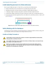
If you are connecting an external Ethernet device such as WiFi or IP camera, appropriate CAT cable
for the protocol to which the Fiber CAP L will connect is required. This model supports a 1000 BASE-T
and 802.3at Class 4 Power over Cat6A Ethernet connection. For the CAT cable, follow the rules in
"Cat6A Cable Requirements for Ethernet Devices” on page 12
–
Per the installation plan, obtain 50
coaxial cables that are of sufficient length to reach from the CAP L
to the passive RF antenna. The end of the 50
coaxial cable that will connect to the ANT connector can
be either a push-pull connector or a threaded connector.
•
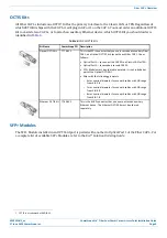
Obtain the Optical OCTIS Kits required for this installation; see
.
•
Obtain SFP+ Module pairs that are appropriate for this installation; see
.
•
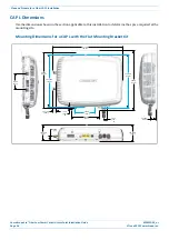
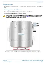
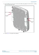
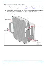
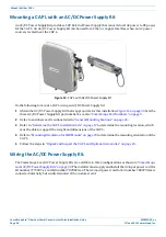
Obtain the Mounting Kits for the installation. Mounting Kits are not included with the CAP L and must be
ordered separately.

