

408-8875
Rev E
2 of 2
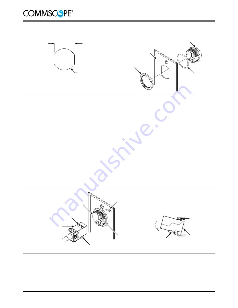
Figure 2
1.3.
Installation
1. Slide the O-ring over the threaded portion of the receptacle. See Figure 2.
2. Insert the threaded portion of the receptacle through the front of the panel or faceplate. Orient the
receptacle in the cutout so that the white arrow indicator on the front of the receptacle is facing up.
See Figure 2.
3. From the back of the panel or faceplate, thread the nut onto the threaded portion of the receptacle.
See Figure 2. Tighten the nut to a torque of 2.26 Nm [20 in.-lb].
4. Refer to Figure 3, and insert the jack or coupler into the receptacle as follows:
a. From the back of the receptacle, align the fixed latch of the jack or coupler with the white arrow
indicator of the receptacle.
b. Tilt the back of the jack or coupler up at a slight angle, and slide it into the opening of the
receptacle. Hook the fixed latch into the slot inside the receptacle.
c. Rotate the back of the jack or coupler down so that the movable latch deflects and locks into the
receptacle.
Figure 3
2.
REVISION SUMMARY
Revisions to this instruction sheet include:
Rebranded to
CommScope
®
Nut
O-Ring
Back of
Faceplate (Ref)
White Arrow Indicator
of Receptacle
Recommended Panel or Faceplate Cutout
Installing Receptacle
Note: Not to Scale
25.65 mm
[1.010 in.]
⌀
28.45 mm
⌀
[1.120 in.]
White Arrow Indicator
of Receptacle
Front of Receptacle
Movable Latch
Jack (Ref)
Slot Inside of
Receptacle
Fixed Latch
Opening of
Receptacle
Fixed Latch
Movable Latch
Rotate
Jack


