© 2019 CommScope, Inc. All rights reserved.
Visit our website at www.commscope.com or contact your local CommScope representative or BusinessPartner for more information.
All trademarks identified by ® or
™ are registered trademarks or trademarks, respectively, of CommScope, Inc. A997-0086 G (5/19)
Page 5 of 8
A997-0086
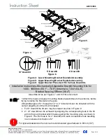
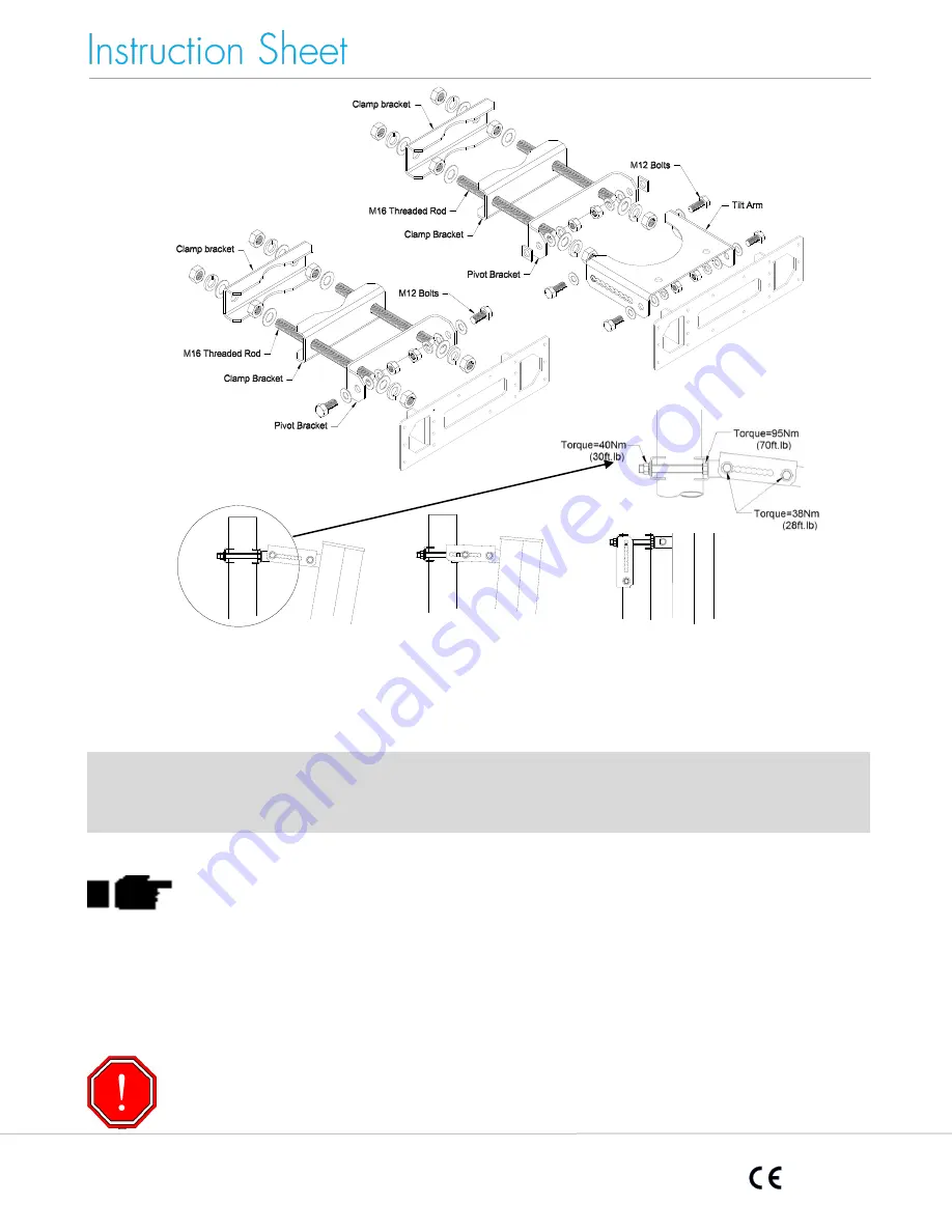
Figure 4: Lower Mounting Bracket Exploded Assembly
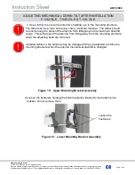
Figure 5: Upper Mounting Bracket Exploded Assembly
Figure 6: Upper Bracket Placement For Various Downtilts
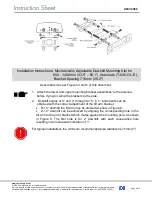
Assemble kit as per Figures 7 and 8 of this document
1.Attach the lower and upper mounting bracket assemblies to the antenna, before
trying to clamp the brackets to the pole.
2.Downtilt angles of 0
through to 12
in 2
increments can be obtained with the
correct adjustment of the tilt arm bracket.
•
For 0
downtilt the tilt arm may be stowed as show in Figure 9.
•
2
- 12
downtilt can be achieved by aligning the corresponding hole in the tilt
arm to the pivot bracket which mates against the mounting pole, as shown in
Figure 9. The first hole is for 2
downtilt, with each consecutive hole resulting
in an increased inclination of 2
.
For typical installations the minimum recommended pipe diameter is 90mm (3.5").
Figure 4.
Figure 5.
Figure 6.
10° Downtilt
5° Downtilt
0° Downtilt
I Installation Instructions-Mechanically Adjustable Downtilt Mounting Kits for
1400 -
1800mm (55.1” – 70.9”) Antenna’s (T-041-GL-E),
Bracket Spacing 976mm (38.4")


