© 2019 CommScope, Inc. All rights reserved.
Visit our website at www.commscope.com or contact your local CommScope representative or BusinessPartner for more information.
All trademarks identified by ® or
™ are registered trademarks or trademarks, respectively, of CommScope, Inc. A997-0086 G (5/19)
Page 8 of 8
A997-0086
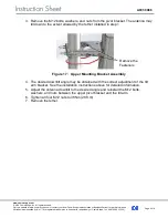
3. Remove the M12 bolts, washers, and nuts from the pivot bracket. The antenna may
tilt down to the extent allowed by the tether installed in step 1.
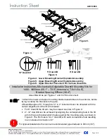
Figure 17: Upper Mounting Bracket Assembly
4. The desired downtilt angle may be obtained
with the correct adjustment of the tilt
arm bracket. See the installation instructions above for detailed information.
5. Adjust the antenna downtilt to the desired angle and reinstall the M12 bolts,
washers, and nuts between the upper pivot bracket and the tilt arm.
6. Tighten all four M12 nuts to 38Nm (28 ft.lb).
7. Remove the tether.
Remove the
Fasteners


