ADCP-96-167 • Issue 5 • July 2016
Page 14
© 2016, CommScope, Inc.
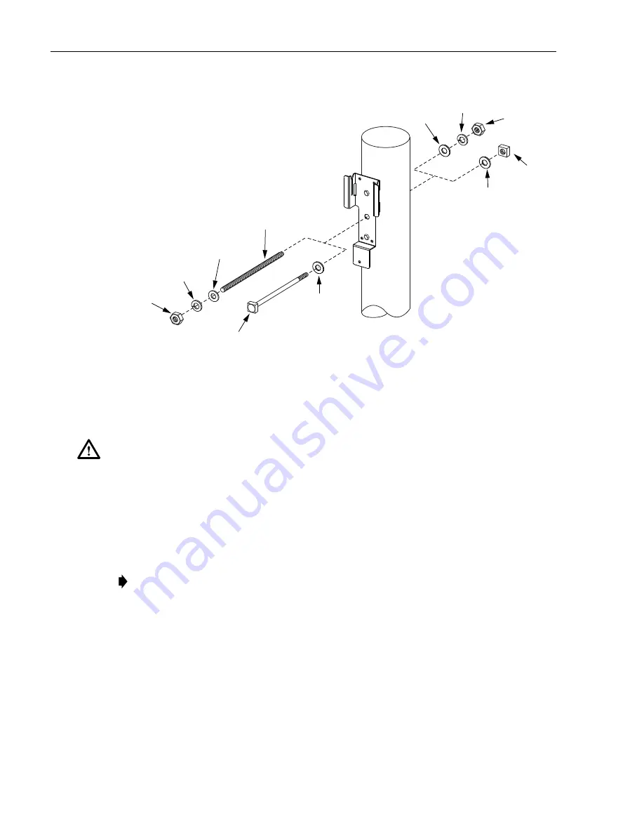
Figure 7. Threaded Rod or Through-Bolt Installation
5. Using appropriate lifting equipment, hoist the cabinet into position for attachment
to the mounting bracket.
6. Hang the cabinet from the installed mounting bracket. The welded bracket on the
back of the cabinet, shown in
, fits into the two slots at the top of the
mounting bracket. The partially installed cap screw at the bottom of the mounting
bracket fits into the slotted tab at the bottom of the cabinet.
7. Tighten the partially installed cap screw at the bottom of the cabinet using the 216B
key tool.
Danger: Do not stand directly under the cabinet as it is being hoisted into position for
mounting. A failure of the lifting equipment could result in serious personal injury.
Note:
A cup washer is included with the cap screw to provide tamper resistance.
24220-A
1/2-INCH
THREADED ROD
1/2-INCH FLAT
WASHER
1/2-INCH FLAT
WASHER
1/2-INCH FLAT
WASHER
1/2-INCH FLAT
WASHER
1/2-INCH LOCK
WASHER
1/2-INCH LOCK
WASHER
1/2-INCH
NUT
1/2-INCH
NUT
1/2-INCH
NUT
1/2-INCH
THROUGH-BOLT
THREADED ROD
INSTALLATION
THROUGH-BOLT
INSTALLATION


