ADCP-96-167 • Issue 5 • July 2016
Page 25
© 2016, CommScope, Inc.
12. Align the gap in the grommet with the space between the clamp yokes and then
tighten the clamp screws evenly to 15 to 17 lbs-force inches (1.7 – 1.9 Nm) of
torque.
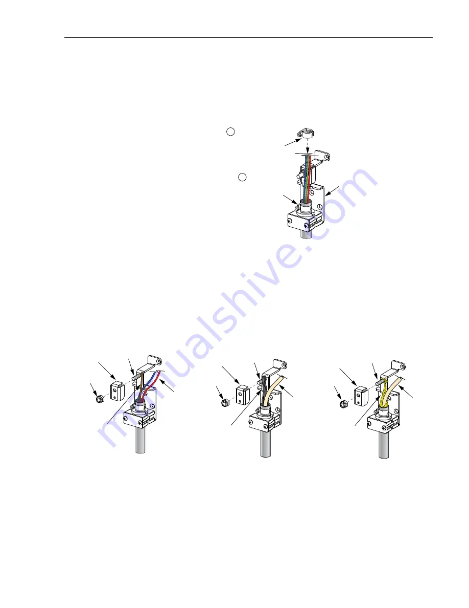
13. If a hose clamp was placed over the cable in step 11 (see
), tighten the
hose clamp to 17 to 19 lbs-force inches (1.7 – 2.1 Nm) of torque.
Figure 16. Hose Clamp Installation
14. Tighten the compression nut on the outside of the cabinet to secure the feeder
cable at the entry point into the cabinet.
15. Disassemble the cable strength member clamp as shown in
. For
stranded cable, the strength member will usually consist of a single element. For
ribbon cable, the strength member may consist of a stranded fiberglass sheath or
yellow synthetic fiber yarn.
Figure 17. Strength Member Clamp Installation
16. If installing cable with a single-element strength member (a), place the strength
member alongside the mounting bracket stud and cut the strength member so it is
flush with the top of the mounting bracket. If installing cable with a stranded
fiberglass sheath (b), gather the sheath together, place it alongside the mounting
24636-A
CLAMP
BRACKET
INSTALL HOSE CLAMP ON ALL OSP
CABLES AND ON ALL IFC CABLES
WITH A CENTRAL STRENGTH MEMBER
TIGHTEN HOSE CLAMP TO
17 - 19 LBS-FORCE INCHES
(1.7 TO 2.1 Nm) OF TORQUE
1
2
24318-C
SINGLE-ELEMENT
STRENGTH
MEMBER
*TIGHTEN NUT TO 35 LBS-FORCE INCHES (4.0 Nm) OF TORQUE
STRENGTH
MEMBER CLAMP
STRANDED
FIBER
BUFFER
TUBES
STUD
FIBER-GLASS
STRENGTH
MEMBERS
STRENGTH
MEMBER CLAMP
RIBBON
FIBER
TUBE
STUD
NUT*
NUT*
NUT*
STRANDED
CABLE
RIBBON
CABLE
RIBBON
CABLE
SYNTHETIC YARN
STRENGTH
MEMBER
STRENGTH
MEMBER CLAMP
RIBBON
FIBER
TUBE
STUD
(a)
(b)
(c)


