background image

HR300 SERIES DEHYDRATOR USER MANUAL 

Page 

9

 of 

12


The first compressor will start and air will begin 
flowing to the transmission line(s). 


If this is a new installation, the transmission 
lines must be purged by creating a small leak at 
the far end of the transmission lines and 
allowing the dehydrator to pump dry air through 
them. 


A minimum of three air volume exchanges is 
required.  If the installation is located in a very 
humid area, up to twelve air exchanges may be 
necessary to properly purge the transmission 
line.  The time, in hours, necessary to exchange 
the air one time is based on the total air volume 
(V) of the waveguide and antenna system. 

Purging time (hours) = (3 x V) / 300, where V is 
line volume in liters 

At the conclusion of the purging cycle, close the 
far end of the transmission lines. 

5.6 

Alarms 

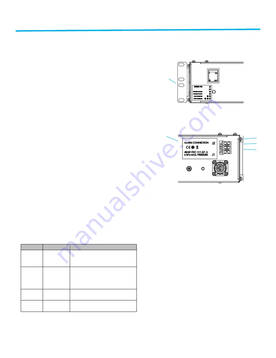
The HR300 is equipped with an LED on the front 

panel for a visual indication of alarm conditions.  
A green LED indicates all is well with the 
dehydrator.  A solid or blinking amber LED 
indicates a problem with the dehydrator. 


Blinks 

Alarm 

Description 

Solid 
Amber 

System 
Failure 

Indicates a failure of the 
controller.  Replacement will be 
necessary. 

High 
Humidity 
(optional) 

Indicates output air is above 10% 
RH.  This can be caused by long 
storage periods and should clear 
in the first 24 hours of operation. 

Low 
Pressure 

Indicates a system pressure 
lower than alarm threshold. 

High 
Pressure 

Indicates a system pressure 
higher than alarm threshold. 


If multiple alarms exist at the same time, they 

will blink in sequence with approximately two 
seconds between. 


Front of Chassis 


Rear of Chassis 


Section 6 

Corrective Maintenance and Spare 
Parts 

The HR300 is designed to be maintenance free.  

If you experience any issues with the HR300, 
please contact CommScope. See Section 8 for 
additional information. 

ALARM 
SYMBOLS 

ALARM 
OUTPUT 

WIRES COLORS 


BLACK (NO) 
WHITE (COM) 
RED (NC) 

Summary of Contents for HR300 Series

Page 1: ...Page 1 of 12 HR300 SERIES DEHYDRATOR USER MANUAL Bulletin AE01B A0595 002 Rev A 2015 CommScope Inc All rights reserved 07 15 ...

Page 2: ...on 6 5 1 Unpacking 6 5 2 Mounting 7 5 2 1 19 Rack Mounting 7 5 2 2 Wall Mounting 7 5 3 Electrical Connections 7 5 3 1 Power Connections 8 5 3 2 Power Connections 8 5 4 Pneumatic Connections 8 5 4 Operation 8 5 6 Alarms 9 Section 6 Corrective Maintenance and Spare Parts 9 Section 7 Outline 10 Section 8 Customer Service 10 8 0 Introduction 10 8 1 In Case of Trouble 11 8 2 Initial Steps by CommScope ...

Page 3: ... must be located such that only authorized personnel have access CAUTION The HR300 utilizes heat to regenerate the drying canisters Mount the HR300 at the top of the equipment rack if possible Should be placed in the top of the equipment rack with nothing mounted above it A minimum gap of at least one rack unit should be left unused above the dehydrator Section 2 Safety Information Make sure that ...

Page 4: ...gh Humidity Alarm 10 RH optional sold separately LED Indications Power on Alarm codes Acoustic Noise 50 dBA Enclosure Degree of Protection IP20 Operating Temperature 5 C to 50 C 23ºF to 122ºF Storage Temperature 40 C to 70 C 40 F to 158 F Power Supply Std 48 60 V DC Power Consumption 45 W Dimensions 2 RU 428 mm x 87 mm x 305 mm 16 85 in x 3 43 in x 12 0 in European Community Directives CE Safety N...

Page 5: ...r B 2 Mounting Brackets B1 6 M4x10 PPH Screws SST Pass B2 6 M4 Flat Washer SST Pass C 1 Power Cable D 30 5 m 100 ft 9 5 mm 3 8 Output Tubing Additional Accessories sold separately HR300 KIT ETSI HR300 ETSI N3 RACK BRACKETS KIT HR150 KIT ACDC HR300 AC TO 48 V DC POWER CONVERTER KIT MT HR KIT HUMIDITY Humidity Sensor Kit ...

Page 6: ...t outlets located on the rear of the chassis Ambient air is drawn through desiccant beds by two low power diaphragm compressors The adsorbent material in the desiccant canisters removes moisture from the ambient air prior to passing it through the internal manifold where the system pressure and humidity level optional is monitored System pressure dictates demand and the HR300 will respond by chang...

Page 7: ...k is not included 5 2 2 Wall Mounting Install the standard 19 rack brackets on the rear of the chassis with the included screws as illustrated below The brackets will provide enough clearance for the tubing and electrical connections Secure the unit to the wall using appropriate fasteners for the wall material The hardware for mounting to the wall is not included 5 3 Electrical Connections Caution...

Page 8: ...orrect have it reversed and then re connect to the dehydrator The HR dehydrators are equipped with reverse polarity protection but will not operate under reverse polarity Polarity for the power cable is Red Positive Black Negative White Ground 5 3 2 Alarm Connections Alarm wiring will need to be provided by the customer at the installation site 5 4 Pneumatic Connections The HR300 has a quantity of...

Page 9: ...ith an LED on the front panel for a visual indication of alarm conditions A green LED indicates all is well with the dehydrator A solid or blinking amber LED indicates a problem with the dehydrator Blinks Alarm Description Solid Amber System Failure Indicates a failure of the controller Replacement will be necessary 1 High Humidity optional Indicates output air is above 10 RH This can be caused by...

Page 10: ...ounting Section 8 Customer Service 8 0 Introduction CommScope provides in warranty and out of warranty repairs as well as dehydrator and compressor overhauls from several Repair Centers Coordination of these services is provided through the nearest Sales Office or Customer Service Center The Center is also prepared to help you with the following Technical Assistance Troubleshooting ...

Page 11: ...uble If the pressurization equipment is suspect they will ask for your unit Model Number and Serial Number check the warranty status of the unit advise the availability of a loaner unit provide an estimate of the cost for inspection and repairs if the unit is out of warranty fax a Return Material Authorization Sheet to you 8 3 Repair Center Process A method of Payment must be provided prior to iss...

Page 12: ...Name and RMA XXXXXXX on outside of the box Address the box to the following Ship To Address CommScope Pressurization Service Center RMA XXXXXXX 11312 S PIPELINE RD EULESS TX 76040 6629 Please note Units received with Biological animal contamination will be returned unrepaired or scrapped after notification and you will be invoiced for inspection and freight CONTACT NUMBERS If you have any question...

Reviews: