


User’s Manual for
ION™-M7P/85P/17P/19P (ML-Cab)
Page 20
MF0143AUA.doc
3.1.3. Pole-Mounting Procedure
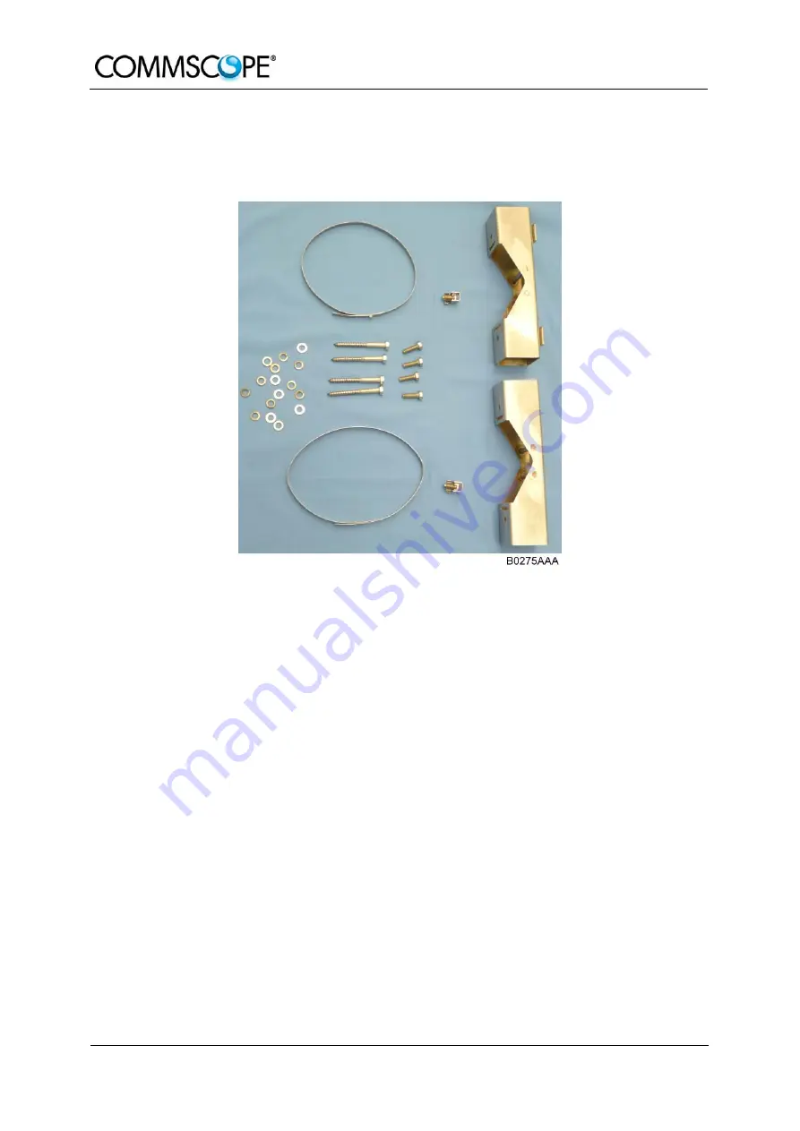
The standard mounting hardware also includes all parts required for pole mounting:
figure 3-3 Pole-mounting kit
Use the screw bands to fasten the two mounting brackets to the pole.
)
Note: When fastening the mounting brackets make sure that they are
installed congruently and not at an angle to each other. To
determine the distance between the beams, refer to the wall
mounting plan that is part of the delivery.
Hang the Remote Unit into the hooks of the upper mounting bracket and screw
the Remote Unit to the lower mounting bracket.
Ensure that there is free access to the electrical connections as well as to the
cabinet. The approved bending radius of the connected cables must not be
exceeded.
Summary of Contents for ION-M7P
Page 1: ...Optical Remote Unit ION M7P 85P 17P 19P ML Cabinet User s Manual MF0143AUA ...
Page 6: ...User s Manual for ION M7P 85P 17P 19P ML cab Page 6 MF0143AUA doc For your notes ...
Page 11: ...1 General Page 11 ...
Page 14: ...User s Manual for ION M7P 85P 17P 19P ML Cab Page 14 MF0143AUA doc For your notes ...
Page 36: ...User s Manual for ION M7P 85P 17P 19P ML Cab Page 36 MF0143AUA doc For your notes ...
Page 44: ...User s Manual for ION M7P 85P 17P 19P ML Cab Page 44 MF0143AUA doc For your notes ...
Page 45: ...6 Appendix Page 45 6 APPENDIX 6 1 ILLUSTRATIONS G3219M0 figure 6 1 Cabinet drawing ...
Page 48: ...User s Manual for ION M7P 85P 17P 19P ML Cab Page 48 MF0143AUA doc For your notes ...
Page 50: ......


