


User’s Manual for
ION™-M7P/85P/17P/19P (ML-Cab)
Page 40
MF0143AUA.doc
With the external alarm inputs it is possible to monitor the status of connected
devices, e.g. a UPS, via software. All alarm inputs are normally high (5 V) without
connection. The polarity (high/ low) can be set via the software at the Master Unit (for
details please see according software manual).
The device to be monitored must be connected so that the alarm contacts will be
closed in case of an alarm (I max = 8 mA). The alarm inputs are potential-free with
common ground.
Subminiature circular connectors series 712 with five and seven contacts, which are
contained in the alarm kit, can be ordered directly from the Binder Connector Group,
the manufacturer, or indirectly from Andrew Solutions. For the designation of the
alarm kit see
V1651A1
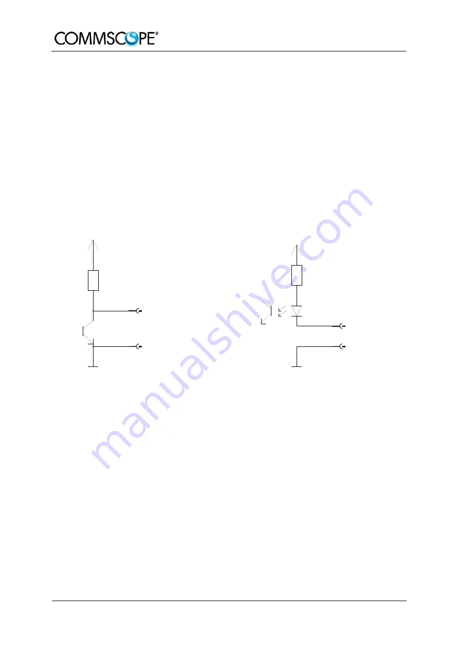
Alarm output
Alarm GND
Alarm GND
Alarm GND
Alarm GND
Alarm input
ION-M alarm outputs
4700R
+5 V
ION-M alarm inputs
+5 V
560R
figure 4-3 Alarm inputs and outputs, standard
4.6.
TROUBLESHOOTING
The status of the Remote Unit can be checked via the Master Unit (for details please
refer to the software manual of the Master Controller). Locally, the status can be
checked at the LED, see chapter
Summary of Contents for ION-M7P
Page 1: ...Optical Remote Unit ION M7P 85P 17P 19P ML Cabinet User s Manual MF0143AUA ...
Page 6: ...User s Manual for ION M7P 85P 17P 19P ML cab Page 6 MF0143AUA doc For your notes ...
Page 11: ...1 General Page 11 ...
Page 14: ...User s Manual for ION M7P 85P 17P 19P ML Cab Page 14 MF0143AUA doc For your notes ...
Page 36: ...User s Manual for ION M7P 85P 17P 19P ML Cab Page 36 MF0143AUA doc For your notes ...
Page 44: ...User s Manual for ION M7P 85P 17P 19P ML Cab Page 44 MF0143AUA doc For your notes ...
Page 45: ...6 Appendix Page 45 6 APPENDIX 6 1 ILLUSTRATIONS G3219M0 figure 6 1 Cabinet drawing ...
Page 48: ...User s Manual for ION M7P 85P 17P 19P ML Cab Page 48 MF0143AUA doc For your notes ...
Page 50: ......


