3 Commissioning
Page 31
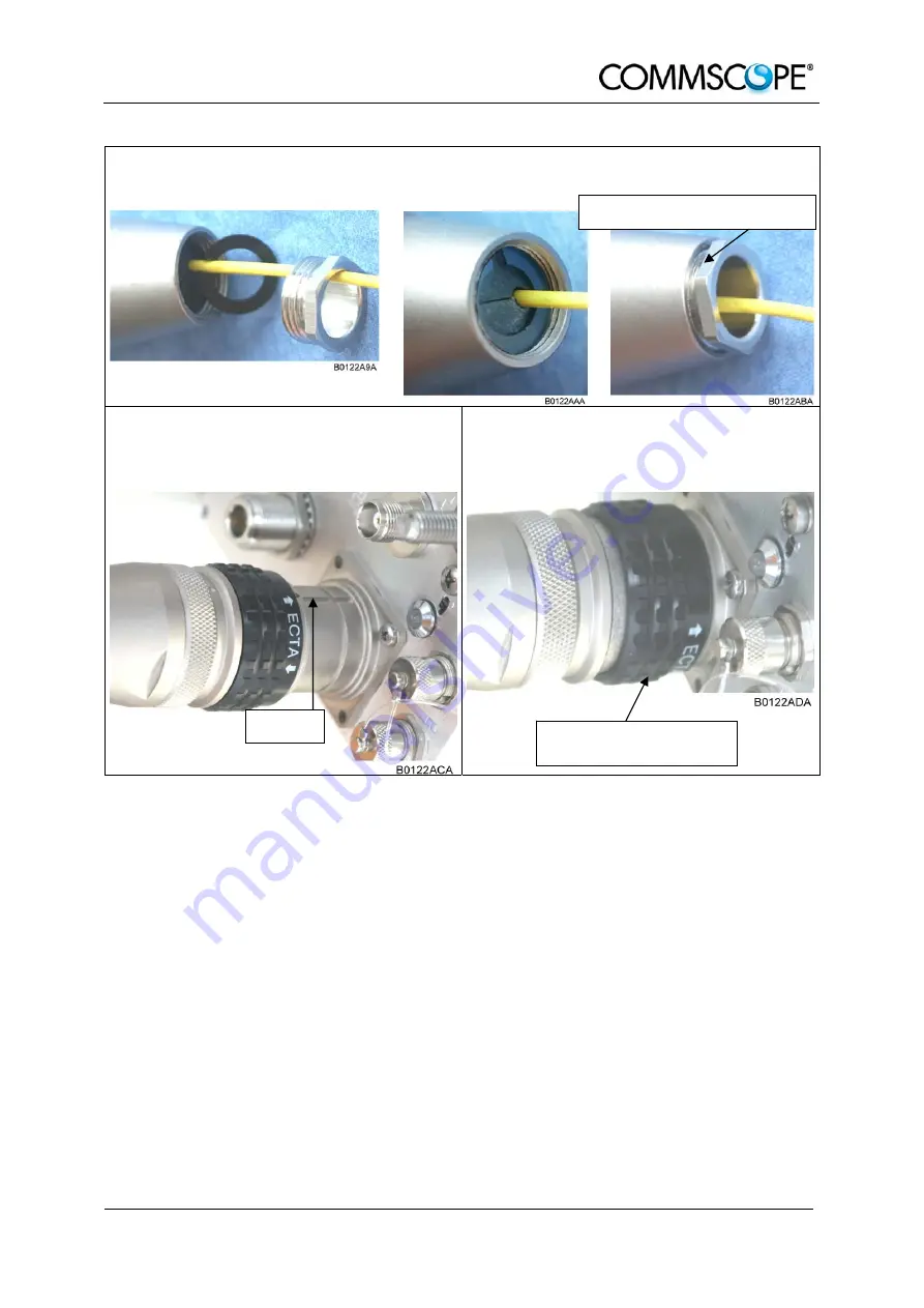
7. Bring the plastic ring over the cable(s), push it into the backshell and compress
the seals and plastic ring by screwing the clamp ring tight (no gap) using a
spanner with opening 20. ***
8. Connect the plug to the optical-fiber
connector of the Remote Unit, again
by fitting a stamp on the plug into the
groove of the connector.
9. To lock the connector, push the black
locking ring forward.****
Screw tight until gap is closed
*** For disassembling, release the clamping ring and remove the seals and the plastic ring first.
**** Locking mechanism: The system of locking the plug is based on a “push-pull” mechanism. The
locking ring has to be pushed forward to lock the connector and pulled back to free the
connection.
3.5.2. Protective-Tube Kit
As additional protection for the optical fibers, this connector type can be
supplemented by a special tube kit. To fasten the tube correctly, first unscrew the
clamp ring (if already installed) of the original plug kit.
Then, proceed according to the following instruction:
Groove
Push forward to lock, pull
back to free connection
Summary of Contents for ION-M7P
Page 1: ...Optical Remote Unit ION M7P 85P 17P 19P ML Cabinet User s Manual MF0143AUA ...
Page 6: ...User s Manual for ION M7P 85P 17P 19P ML cab Page 6 MF0143AUA doc For your notes ...
Page 11: ...1 General Page 11 ...
Page 14: ...User s Manual for ION M7P 85P 17P 19P ML Cab Page 14 MF0143AUA doc For your notes ...
Page 36: ...User s Manual for ION M7P 85P 17P 19P ML Cab Page 36 MF0143AUA doc For your notes ...
Page 44: ...User s Manual for ION M7P 85P 17P 19P ML Cab Page 44 MF0143AUA doc For your notes ...
Page 45: ...6 Appendix Page 45 6 APPENDIX 6 1 ILLUSTRATIONS G3219M0 figure 6 1 Cabinet drawing ...
Page 48: ...User s Manual for ION M7P 85P 17P 19P ML Cab Page 48 MF0143AUA doc For your notes ...
Page 50: ......


