www.commscope.com
860106368
Issue 6, December 2012
Page 5 of 12
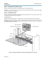
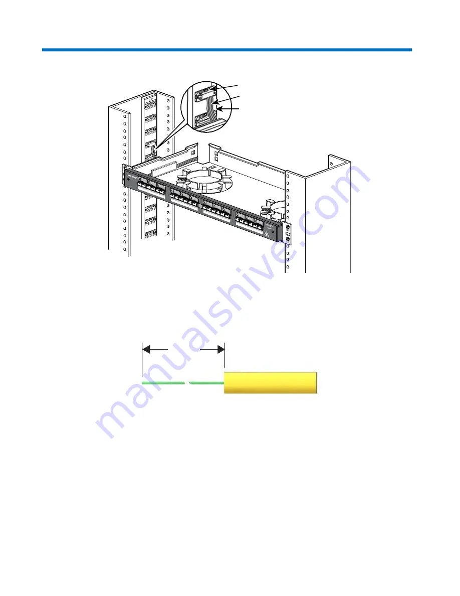
Figure 3 Connecting the Panel Bus Jumper to the Panel Bus
Step 3 – Installing Cable
Directions are provided in the sections below for preparing the fiber optic cable and connecting it to the faceplate
connectors.
Figure 4 Preparing the Cable for Splicing or Termination
Preparing the Cable for Splicing or Termination
Whether you are splicing or terminating the fiber optic cable, prepare the cable as shown in Figure 4.
Prepare the fiber optic cable for connection to the faceplate either by splicing or terminating the cable.
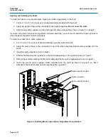
For instructions, see “Splicing and Installing the Cable” on page 6 or “Terminating and Installing the Cable” on
page 9.
Buffered fiber
Fiber optic cable
42 in
(106.7cm)
Panel bus jumper
Polarized tab
Panel bus

